
Control method, control device, storage medium and remote controller

A control method and technology of a control device, applied in the direction of instruments, signal transmission systems, non-electrical signal transmission systems, etc., can solve the problems of large volume, large space occupation, large error of low-frequency oscillation circuit, etc.

Active Publication Date: 2018-06-29
GD MIDEA AIR-CONDITIONING EQUIP CO LTD
View PDF13 Cites 5 Cited by
  • Summary
  • Abstract
  • Description
  • Claims
  • Application Information

AI Technical Summary

Problems solved by technology

However, due to the large error of the low-frequency oscillation circuit inside the MCU, the error is generally more than 10%, and sometimes it can reach 15%. Therefore, in order to reduce the timing error, the remote controller with a longer time timing function will be connected with an external crystal oscillator, such as The 32.768K crystal oscillator has the advantage of high precision, but it has the disadvantage of taking up a lot of space due to its large size, and in the production process of the remote control, the additional external oscillator will also affect the production efficiency and production cost optimization of the product

Method used


Image

  • Control method, control device, storage medium and remote controller
  • Control method, control device, storage medium and remote controller
  • Control method, control device, storage medium and remote controller

Examples


Embodiment Construction

[0038] In order to understand the above-mentioned purpose, features and advantages of the present invention more clearly, the present invention will be further described in detail below in conjunction with the accompanying drawings and specific embodiments. It should be noted that, in the case of no conflict, the embodiments of the present application and the features in the embodiments can be combined with each other.

[0039] In the following description, many specific details are set forth in order to fully understand the present invention. However, the present invention can also be implemented in other ways different from those described here. Therefore, the protection scope of the present invention is not limited by the specific details disclosed below. EXAMPLE LIMITATIONS.

[0040] Combine below figure 1 and figure 2 The control method of the remote controller according to the first embodiment of the present invention will be described in detail.

[0041] Such as fi...


PUM


Abstract

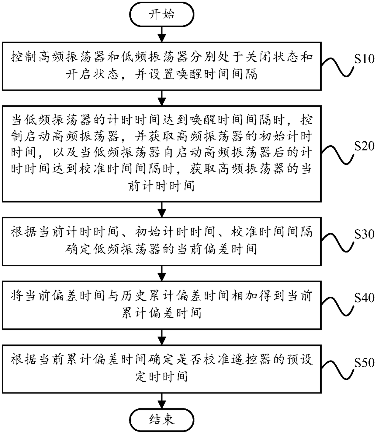
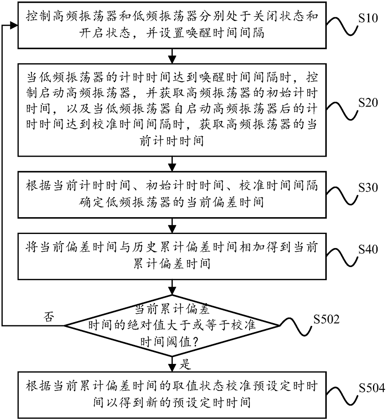
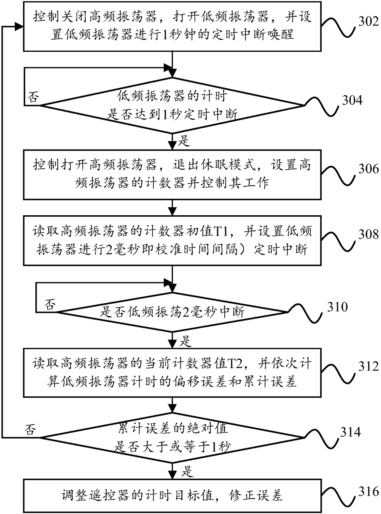
The invention provides a control method of a remote controller. The remote controller includes a control chip internally provided with a high frequency oscillator and a low frequency oscillator. The control method includes the following steps: controlling the high frequency oscillator and the low frequency oscillator to be in an off state and an on state respectively, and setting a wake-up time interval; controlling to start the high frequency oscillator and obtaining the initial timing time when the timing time of the low frequency oscillator reaches the wake-up time interval, and obtaining the current timing time of the high frequency oscillator when the timing time of the low frequency oscillator after the starting of the high frequency oscillator reaches a calibration time interval; determining the current deviation time of the low frequency oscillator according to the current timing time, the initial timing time and the calibration time interval; adding the current deviation timeto a historical cumulative deviation time to obtain the current accumulative deviation time; and determining whether to calibrate the preset timing time of the remote controller or not according to the current accumulative deviation time. The invention also provides a control device of the remote controller, a computer readable storage medium, and the remote controller.

Description

technical field [0001] The present invention relates to the technical field of household electrical appliances, in particular to a control method for a remote controller, a control device for a remote controller, a computer-readable storage medium and a remote controller. Background technique [0002] At present, the remote controllers with liquid crystal displays of most household appliances need to enter the sleep mode during static work due to their low power consumption requirements. low frequency oscillating circuit. However, due to the large error of the low-frequency oscillation circuit inside the MCU, the error is generally more than 10%, and sometimes it can reach 15%. Therefore, in order to reduce the timing error, the remote controller with a longer time timing function will be connected with an external crystal oscillator, such as The 32.768K crystal oscillator has the advantage of high precision, but has the disadvantage of taking up a lot of space due to its l...

Claims


Application Information

Patent Timeline
IPC IPC(8): G08C23/04G08C25/00
CPCG08C23/04G08C25/00
Inventor 彭永森
Owner GD MIDEA AIR-CONDITIONING EQUIP CO LTD
Learn More