Cylindrical oil tank structure transformer

A technology for transformers and oil tanks, applied in the field of transformers, can solve the problems of poor sealing between the tank cover and the oil tank, oil leakage, waste, etc., and achieve the effects of improving mechanical connection strength, eliminating assembly errors, and ensuring safe operation.

Inactive Publication Date: 2018-06-29
CEEG JIANGSU
View PDF0 Cites 0 Cited by
  • Summary
  • Abstract
  • Description
  • Claims
  • Application Information

AI Technical Summary

Problems solved by technology

[0002] During the general assembly of the transformer with cylindrical oil tank structure, the tank cover is used to lift the body and put it into the oil tank together. The traditional connection method of the body box cover is as follows: figure 1 As shown, there are the following defects: (1) Because this structure utilizes the transverse shear force of the connecting bolts, in order to ensure the mechanical strength, the selected diameter is larger, and there is waste; (2) During the process of lowering the box and after installation, it is impossible to Clearly observe whether the bottom of the body is in full contact with the bottom of the oil tank. Due to the accumulation of errors caused by various links in the manufacturing process, there are situations where the body is suspended in the air or the height of the body is slightly higher than the oil tank. The former seriously affects the operation safety of the transformer, while the latter The seal between the tank cover and the oil tank is not tight, and the problem of oil leakage, and this error cannot be corrected and eliminated in the later stage; (3) For the transformer that needs to be grounded separately for the iron core and the clamp, under the action of transverse shear force, the sleeve is connected The insulating material on the bolts used to insulate the box cover and clamps is very easily damaged, resulting in multi-point grounding

Method used


Image

  • Cylindrical oil tank structure transformer
  • Cylindrical oil tank structure transformer

Examples


Embodiment Construction

[0017] The present application will be described in detail below in conjunction with specific embodiments.

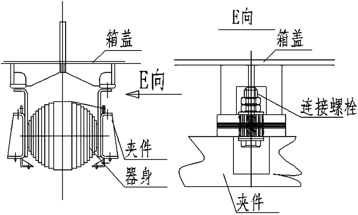
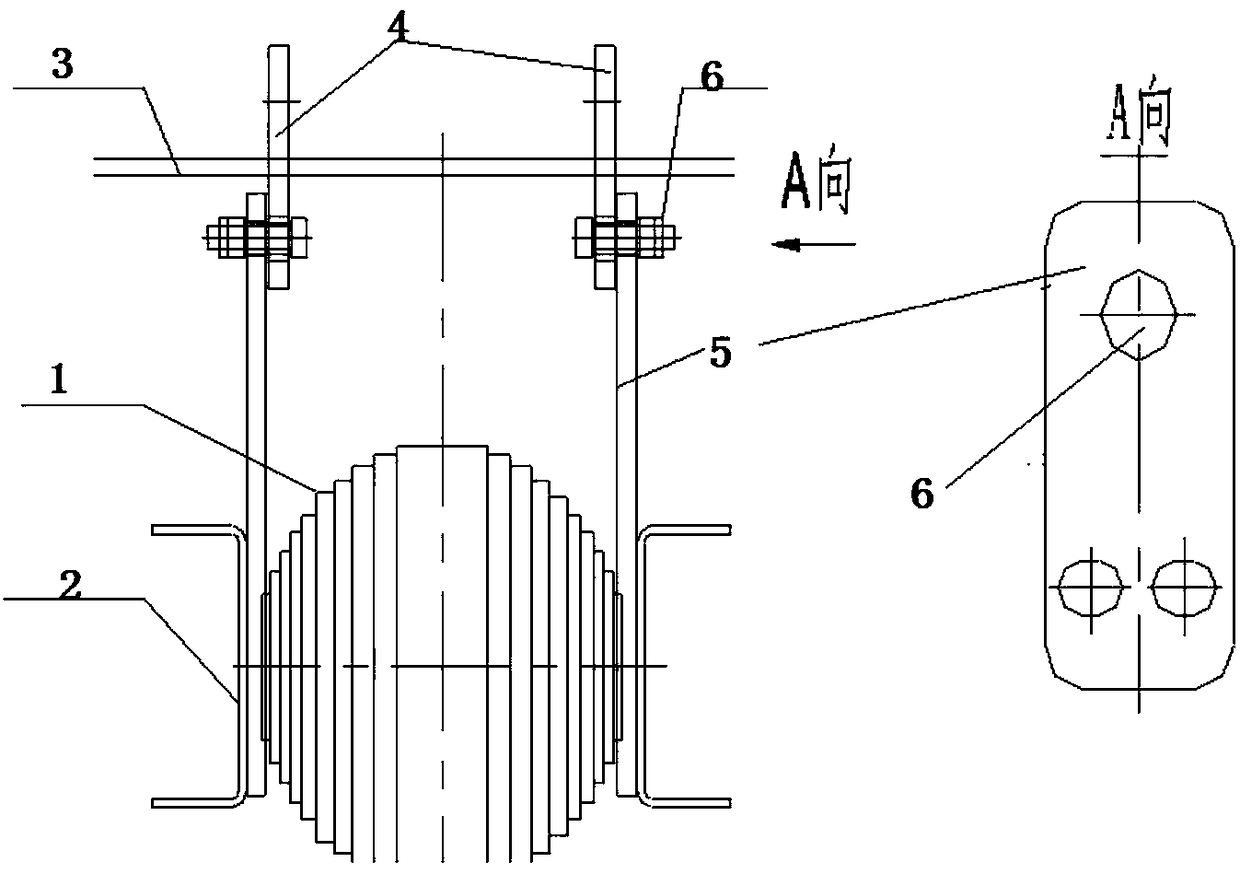
[0018] Such as figure 2 The shown cylindrical oil tank structure transformer includes a body 1, clips 2 placed on both sides of the body 1, and a tank cover 3, the tank cover 3 is provided with a first connecting piece 4 extending downward, so The clamping piece is provided with a second connecting piece 5 extending upwards, and the first connecting piece and the second connecting piece are fixed by transverse connecting bolts 6 . The size of the connecting bolt 6 is generally M16-M24, and the clips 2 on both sides of the device body and the device body 1 are connected and fixed by a pull screw. The connecting bolt 6 is sheathed with an insulating material for insulating the case cover and the clip, specifically a phenolic paper tube. In order to meet the requirements of different sizes of the body, an adjustment support plate can also be added between the first conn...


PUM


Abstract

The invention discloses a cylindrical oil tank structure transformer. The cylindrical oil tank structure transformer comprises a transformer body, clamping pieces arranged on the two sides of the transformer body, and a tank cover; first connecting pieces extending downwards are arranged on the tank cover, second connecting pieces extending upwards are arranged on the clamping pieces, and the first connecting pieces and the second connecting pieces are fixed through transverse connecting bolts. Compared with the prior art, the cylindrical oil tank structure transformer has the advantages thatthe mechanical connection strength is improved; assembly errors caused by various production links to general assembly are reduced; for double-grounding transformers, the risk of multi-point groundingis lowered.

Description

technical field [0001] The invention belongs to the technology of transformers, in particular to a transformer with a cylindrical oil tank structure. Background technique [0002] During the general assembly of the transformer with cylindrical oil tank structure, the tank cover is used to lift the body and put it into the oil tank together. The traditional connection method of the body box cover is as follows: figure 1 As shown, there are the following defects: (1) Because this structure utilizes the transverse shear force of the connecting bolts, in order to ensure the mechanical strength, the selected diameter is larger, and there is waste; (2) During the process of lowering the box and after installation, it is impossible to Clearly observe whether the bottom of the body is in full contact with the bottom of the oil tank. Due to the accumulation of errors caused by various links in the manufacturing process, there are situations where the body is suspended in the air or t...

Claims


Application Information

Patent Timeline
IPC IPC(8): H01F27/26
CPCH01F27/266
Inventor 王凯郑会奇傅高金
Owner CEEG JIANGSU
Why Eureka
Try Eureka