Hybrid multibeam antenna

A multi-beam antenna and beam technology, which is applied to antennas, antenna arrays, and antenna arrays that are powered independently, can solve the problems of large volume, wide antenna width, and insufficient capacity, so as to improve network capacity, reduce interference, and solve insufficient capacity. problem effect

Pending Publication Date: 2018-06-29
GUANGDONG BROADRADIO COMM TECH
View PDF8 Cites 3 Cited by
  • Summary
  • Abstract
  • Description
  • Claims
  • Application Information

AI Technical Summary

Problems solved by technology

[0004] The existing Chinese patent No. 201621099895.X proposes a dual-frequency two-beam antenna, but because the antenna has two beams for low frequency and high frequency, the antenna has a wide width and a large volume, and some frequency bands are traditional The single-beam base station antenna can meet its coverage requirements, so it is necessary to develop a miniaturized antenna that can meet both coverage and insufficient capacity

Method used


Image

  • Hybrid multibeam antenna
  • Hybrid multibeam antenna
  • Hybrid multibeam antenna

Examples


Embodiment 1

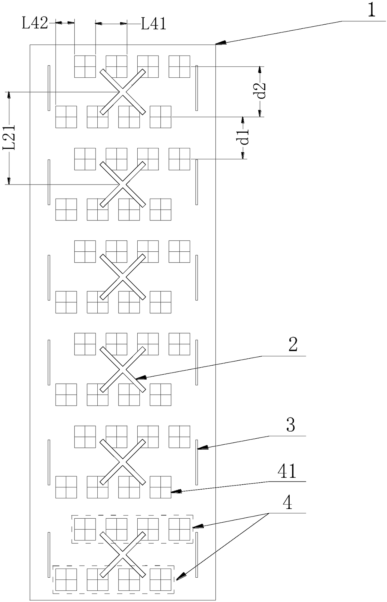
[0026] The hybrid multi-beam antenna in this embodiment works in two wide frequency bands, low frequency (694-960 MHz) and high frequency (1695-2690 MHz).

[0027] Such as figure 1 As shown, a hybrid multi-beam antenna in this embodiment includes a reflector 1 , and a low-frequency base station antenna array and a high-frequency two-beam antenna array mounted on the reflector 1 . Among them, the low-frequency base station antenna array and the high-frequency two-beam antenna array form the conventional base station single-beam antenna and two-beam antenna respectively, so that the antennas of different systems working in different frequency bands share the reflector and radome, and realize the integration of multiple systems The design is conducive to the miniaturization of the antenna and saves installation space.

[0028] Among them, the low-frequency base station antenna array and the high-frequency two-beam antenna array are nested with each other, and the low-frequency b...

Embodiment 2

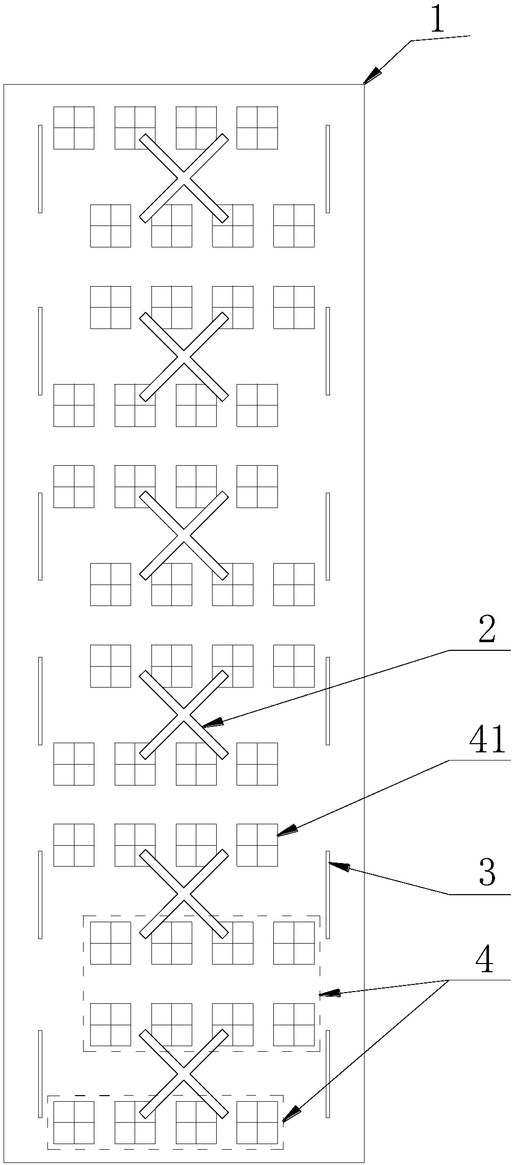
[0036] The arrangement of the low-frequency base station antenna array in a hybrid multi-beam antenna in this embodiment is the same as that in Embodiment 1; the high-frequency two-beam antenna array is composed of seven high-frequency radiation unit subarrays 4, and adjacent high-frequency Radiation unit sub-arrays 4 are arranged in a staggered horizontal direction; the first and last high-frequency radiation unit sub-arrays 4 are each composed of a row of high-frequency radiation units 41, and the middle high-frequency radiation unit sub-arrays 4 are each composed of two rows of high-frequency radiation units 41 Composition, two rows of high-frequency radiation units 41 are arranged without offset in the horizontal direction. see details figure 2 . The column spacing of the high-frequency radiation unit 41 in the same row is the same as that in the first embodiment, the staggered spacing of the adjacent high-frequency radiation unit sub-arrays 4 is the same as that in the ...

Embodiment 3

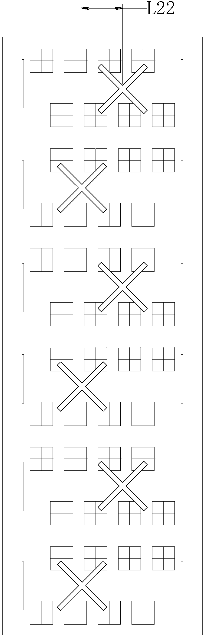
[0038] The arrangement of the high-frequency two-beam antenna array in a hybrid multi-beam antenna in this embodiment is the same as that in Embodiment 2; the low-frequency base station antenna array is formed by six low-frequency radiation units arranged in an S shape, and two adjacent low-frequency radiation The horizontal offset distance between units is L22, which is about one-sixth of the low-frequency central wavelength. For details, see image 3 , the vertical distance between two adjacent low-frequency radiation units is the same as that in Embodiment 2.


PUM


Abstract

The invention discloses a hybrid multibeam antenna. The hybrid multibeam antenna comprises a reflection board, a low-frequency base station antenna array and a high-frequency two-beam antenna array, wherein the low-frequency base station antenna array and the high-frequency two-beam antenna array are arranged on the reflection board and are embedded with each other. The low-frequency base stationantenna array consists of a low-frequency radiation unit; the high-frequency two-beam antenna array consists of at least three high-frequency radiation unit subarrays which are arranged in a staggeredway along a horizontal direction; each high-frequency radiation unit subarray consists of high-frequency radiation units which are arranged linearly in less than three rows along the vertical direction and the horizontal direction. By adopting the hybrid multibeam antenna, the problem of signal coverage can be solved by forming a single-beam base station antenna in an ultrawide-frequency low-frequency band; the problem of insufficient capacity can be solved through forming the two-beam antenna in an ultrawide frequency high-frequency band, and full-band communication is realized.

Description

technical field [0001] The invention relates to the technical field of communication, in particular to a hybrid multi-beam antenna. Background technique [0002] With the rapid development of the mobile Internet, the data traffic in the mobile communication network surges, which puts a huge pressure on the bandwidth capacity of mobile communication, especially in densely populated areas. For example, large squares in urban areas, transportation hubs, open stadiums, large sports venues, art performance venues, tourist attractions, college dormitory buildings, etc., the data traffic in these areas is huge, and the bandwidth capacity of the mobile communication network is difficult to meet the requirements of the mobile Internet. The demand for image and video services in China affects the user's Internet access speed and experience. In order to expand the network capacity, the traditional solution adopts reducing the coverage area of ​​the antenna and increasing the carrier. ...

Claims


Application Information

Patent Timeline
Patent Type & Authority Applications(China)
IPC IPC(8): H01Q19/10H01Q21/06H01Q21/08H01Q21/30
CPCH01Q19/10H01Q21/061H01Q21/08H01Q21/30
Inventor 张劭吴壁群孙丹吴泽海苏振华
Owner GUANGDONG BROADRADIO COMM TECH
Why Eureka
Try Eureka