A camera configuration method and device
A configuration method and camera technology, applied in the field of computer vision, can solve the problem of not considering other factors, and achieve the effect of ensuring the effect of motion capture, the configuration method is reasonable, and the configuration is economical and reasonable.
- Summary
- Abstract
- Description
- Claims
- Application Information
AI Technical Summary
Problems solved by technology
Method used
Image
Examples
Embodiment 1
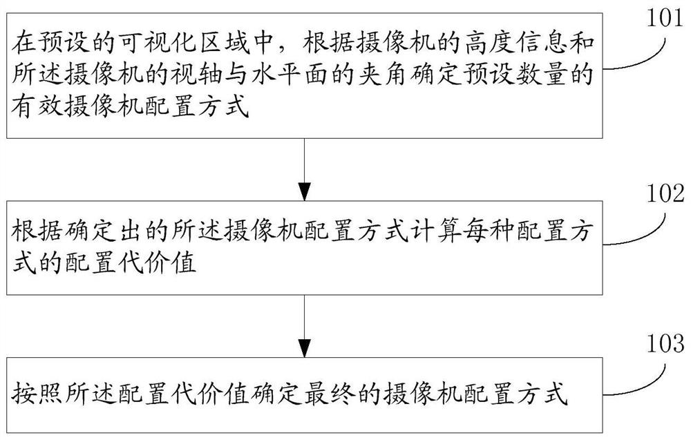
[0031] figure 1 It is a flowchart of a camera configuration method provided in Embodiment 1 of the present invention. The execution subject of this embodiment may be a computer device or a functional unit in the computer device. This embodiment specifically includes steps S101 to S103, which are described in detail as follows:
[0032] S101: In the preset visualization area, determine a preset number of valid camera configuration modes according to the height information of the cameras and the angle between the visual axis of the cameras and the horizontal plane.
[0033] The preset visualization area can be any size created by the user in the optical motion capture system, and contains the simulated area of obstacles such as columns and walls. In the preset visualization area, the user can further set camera parameters, including the set total number of cameras, and the set total number of cameras can be actually adjusted.
[0034] The camera configuration mode can be dete...
Embodiment 2
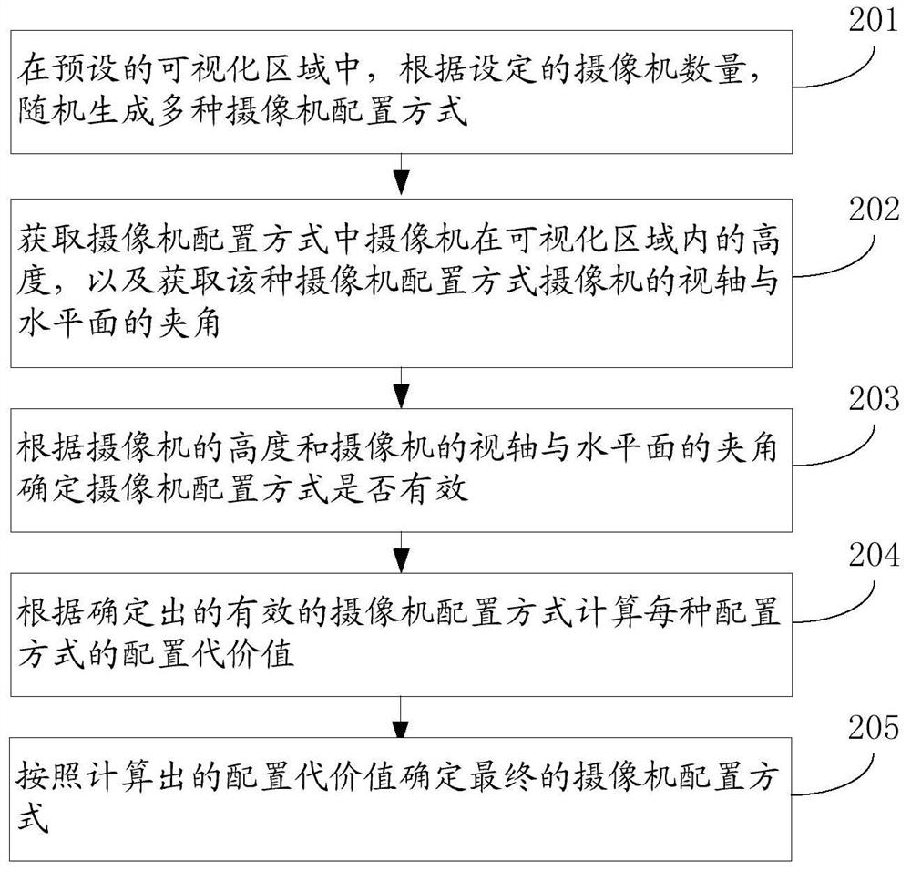
[0059] figure 2 It is a flow chart of a camera configuration method provided in Embodiment 2 of the present invention. The execution subject of this embodiment may be a computer device or a functional unit in a computer device. The difference between this embodiment and Embodiment 1 is that the detailed description How to determine a preset number of effective camera configurations according to the height information of the cameras and the angle between the visual axis of the cameras and the horizontal plane, that is, this embodiment specifically describes step S101. The details are as follows:
[0060] S201: In the preset visualization area, randomly generate multiple camera configuration modes according to the set number of cameras.
[0061] The preset visualization area can be any size created by the user in the optical motion capture system, and contains the simulated area of obstacles such as columns and walls. In the preset visualization area, the user can further s...
Embodiment 3
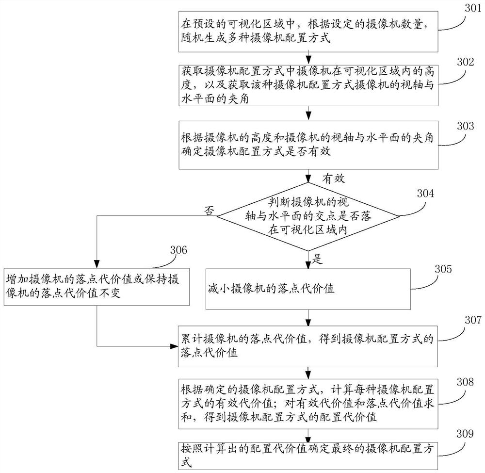
[0080] image 3 It is a flow chart of a camera configuration method provided by Embodiment 3 of the present invention. For Embodiment 3, reference may be made to Embodiment 2. For steps S301-303, reference may be made to Steps S201-203 in Embodiment 2, which will not be repeated here.
[0081] The difference between the third embodiment and the second embodiment is that, after calculating the configuration cost value of each configuration mode according to the determined effective camera configuration mode, when calculating the configuration cost value of each configuration mode, the effective camera configuration mode is also considered In , whether the intersection of the camera boresight and the horizontal plane falls within the visualization area affects the configuration cost value. That is to say, when calculating the configuration cost value of the camera configuration mode, in addition to considering the number of visible cameras at the point to be tested and the relat...
PUM
 Abstract
Description
Claims
Application Information
 - R&D
- Intellectual Property
- Life Sciences
- Materials
- Tech Scout
- Unparalleled Data Quality
- Higher Quality Content
- 60% Fewer Hallucinations
Browse by: Latest US Patents, China's latest patents, Technical Efficacy Thesaurus, Application Domain, Technology Topic, Popular Technical Reports.
© 2025 PatSnap. All rights reserved.Legal|Privacy policy|Modern Slavery Act Transparency Statement|Sitemap|About US| Contact US: help@patsnap.com


