Hydraulic hoisting monitor system and its use in hydraulic hoisting control

A technology of hydraulic lifting and monitoring system, applied in general control system, control/regulation system, program control in sequence/logic controller, etc. It can achieve the effects of good remote controllability and real-time performance, reasonable system configuration, and powerful design functions.

Active Publication Date: 2007-06-27
LIUZHOU OVM MASCH CO LTD
View PDF1 Cites 21 Cited by
  • Summary
  • Abstract
  • Description
  • Claims
  • Application Information

AI Technical Summary

Problems solved by technology

It requires the operator to have a good understanding of the working conditions of the system, and at the same time be very familiar with binary coding, otherwise it is very likely to misuse and cause serious consequences
Because there are too many switches and relays (the selection of jacks and pumping stations is realized by the combination of switches and relays), the wiring of electrical appliances is complicated, which increases the workload of equipment maintenance
[0004] 2. The jacks, pumping stations and laser instruments working in the system are all controlled and operated by PC1. There is no problem in the normal lifting and lowering process, but it brings great difficulties to the construction personnel during the installation and debugging of the equipment. ;Because all kinds of detection sensors are installed on site, it needs to be adjusted repeatedly to find the best position, and the console is far away from the site, so the installers cannot operate it. In addition, the communication mode between PC1 and other PCs is adopted, and the communication speed is less than The speed of direct operation of the hardware, so the time spent on installation and debugging is several times that of on-site operation (local control)
[0005] 3. The purpose of using the camera system and the TV monitoring system is to let the operator understand the scene, but because the camera system must have a suitable position and angle to install the camera, and the jack and pump station of the hydraulic lifting system are installed tens of meters or even hundreds of meters away. The height of the hydraulic lifting system is generally used in the construction occasions with narrow space, so it is difficult to provide a platform on site that is convenient for installing jacks and pumping stations and cameras. The economy is also difficult to really play the expected role
[0006] 4. Since there is a certain distance between the pump station and the jack, there is oil loss, so installing the oil pressure detection sensor on the pump station (power system) cannot really reflect the size of the load
[0007] 5. The laser rangefinder communicates with the programmable controller through RS232. Although the photoelectric isolator is used to extend the transmission distance, the RS232 interface can only communicate point-to-point. Each programmable controller can only connect to one laser, and multiple lasers cannot be connected The laser is connected to a programmable controller, so the flexibility and field adaptability are poor
[0008] 6. The data during the upgrading process is not saved in the database, so it is impossible to analyze and summarize the on-site data afterwards, which is not conducive to the improvement of the system

Method used


Image

  • Hydraulic hoisting monitor system and its use in hydraulic hoisting control
  • Hydraulic hoisting monitor system and its use in hydraulic hoisting control
  • Hydraulic hoisting monitor system and its use in hydraulic hoisting control

Examples


Embodiment 1

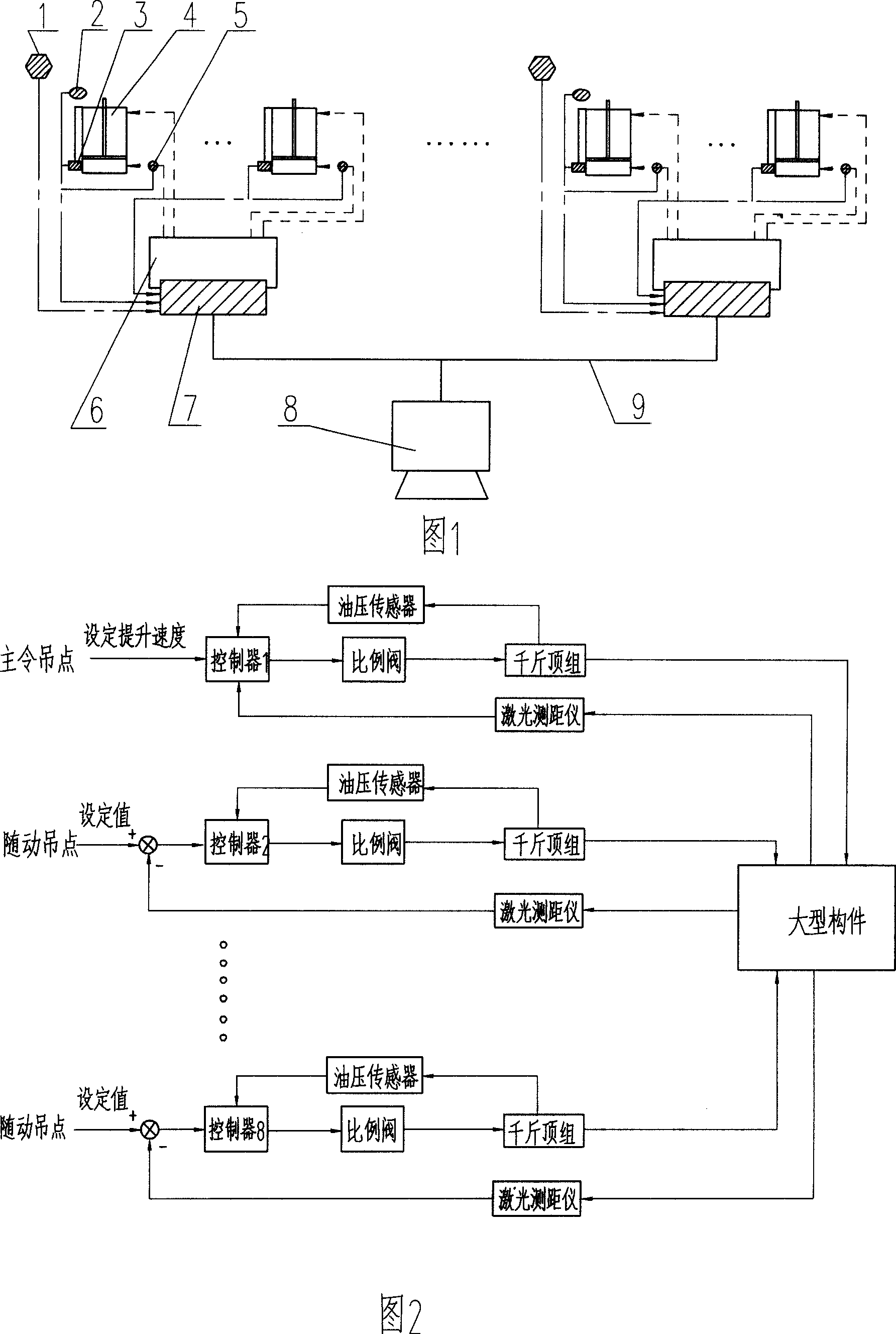
[0050] A hydraulic lifting monitoring system is composed of an upper computer, a lower computer and a data acquisition system. The upper computer 8 is a monitoring computer with monitoring software to realize system monitoring and data management, and the lower computer is written in 8 field controllers 7 composed of 8 programmable controllers with logic control main program and synchronous adjustment subroutine, 8 field controllers 7 are respectively installed on 4 hydraulic pump stations 6, and communicate with the monitoring computer through the real-time network Connected, each site controller 7 controls 4 hydraulic lifting jacks, and the data acquisition device includes a displacement sensor 3 installed on the main top of each jack 4 for detecting piston displacement, a pressure sensor 5 for detecting the pressure of the oil inlet, The proximity switch group 2 installed on the upper and lower anchorages to detect the tightness of the anchorage and the laser instrument 1 in...

Embodiment 2

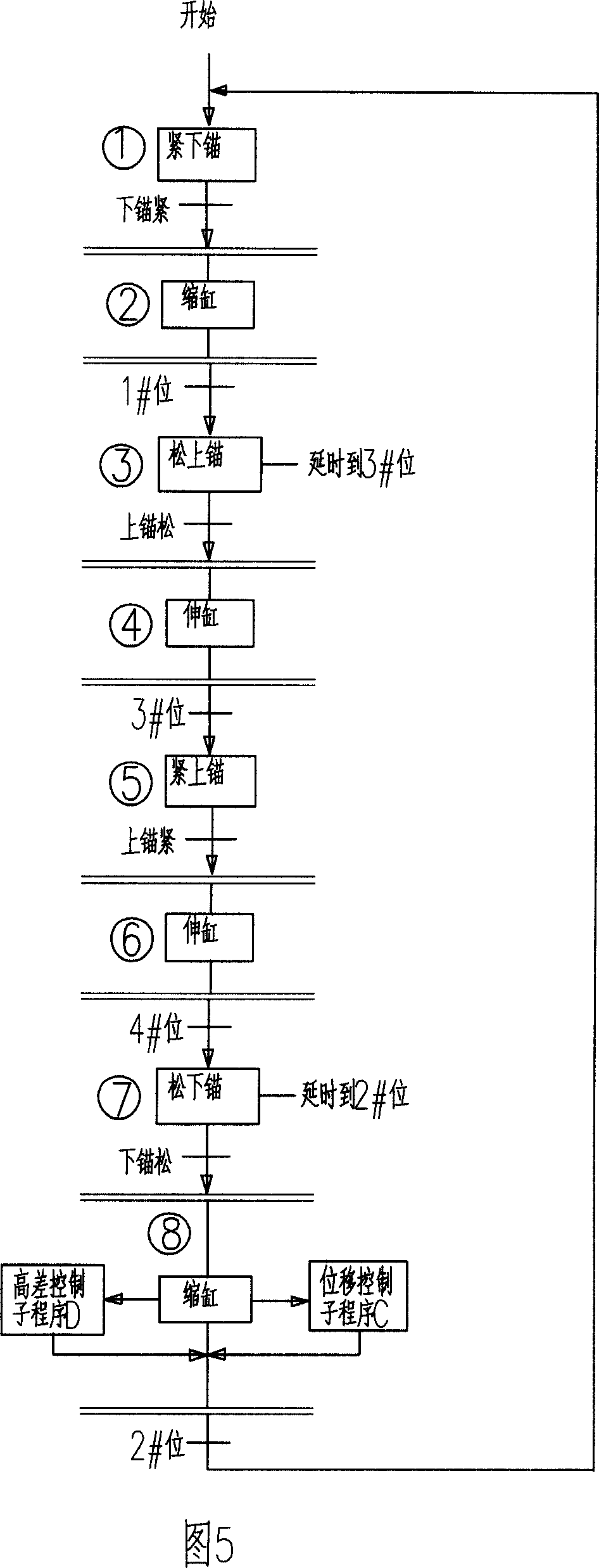
[0055] The application of the above-mentioned hydraulic lift monitoring system to hydraulic lift control—that is, the method of using the above-mentioned hydraulic lift monitoring system for hydraulic lift control.

[0056] The method that the lifting monitoring system is used for hydraulic lifting control is a system control method, and the system control includes a remote control mode and a local control mode:

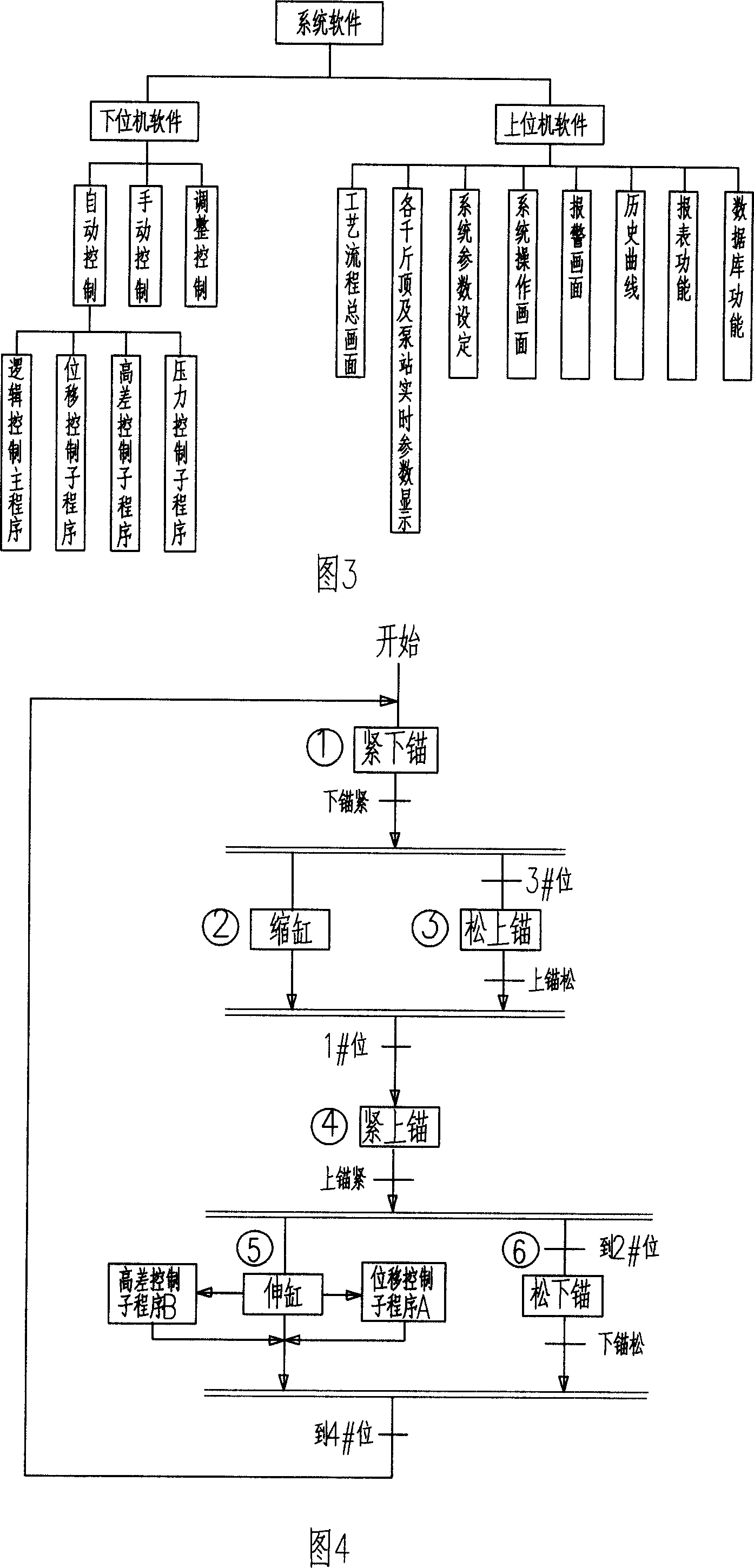
[0057] The remote control mode is the highest level of the system. All operations are completed on the host computer—monitoring computer. At this time, the operations of all on-site controllers are invalid. Manual and automatic control to complete effective controls such as lifting, lowering, anchor tightening, and anchor loosening; the maximum pressure of each platform can be set to ensure the safety of the system, and the extension cylinder of the jack can also be changed by changing the opening size of the proportional valve , Shrink cylinder speed.

[0058] The ...


PUM


Abstract

The monitored control (MC) system is composed of up device, low device and data acquisition system. The up device is a MC computer with monitored control software in use for monitored controlling system and data management. The low device includes n pieces of site controller composed of n pieces of programmable controller with logic control main program and synchronous adjustment sub program being written into. Being installed on y pieces of hydraulic power unit, the n pieces of site controller through real time network is connected to MC computer. The method includes remote control mode, and local control mode. No mater how large the system is, direct selecting mode for jacks is adopted in the system. Features are: simple system circuit, intuitive operations, and accurate measurement. Configuration software is in use for monitoring system and querying historical data. The invention is in use for lifting control of large-scale component.

Description

Technical field: [0001] The invention relates to a hydraulic lifting monitoring system and its application in hydraulic lifting control. Background technique [0002] The hydraulic lifting system is a new type of lifting equipment integrating machine, electricity and hydraulic. Compared with conventional hoisting tools of the same tonnage, it is small in size, light in weight, and occupies a small space. It is especially suitable for construction occasions where the space is narrow and conventional hoisting tools cannot enter. The hydraulic lifting system that is widely used in the installation of equipment in the power construction, petrochemical, and shipbuilding industries and the lifting of roads and bridges is still dominated by logic-controlled lifting systems. This type of system is simple in structure and cheap in price, but cannot be adjusted dynamically and synchronously, and is suitable for smaller projects with low requirements. In recent years, there have also...

Claims


Application Information

Patent Timeline
Patent Type & Authority Applications(China)
IPC IPC(8): G05B19/05G05B15/02G05D3/12B66F3/22B66F17/00
Inventor 甘秋萍陈旭明李兴奎吴志勇
Owner LIUZHOU OVM MASCH CO LTD
Why Eureka
Try Eureka