
Fixture for machining of circuit board

A technology of circuit boards and fixtures, applied in the direction of manufacturing tools, workpiece clamping devices, etc., can solve problems such as lack of universality, single function, and economic loss, and achieve the effects of avoiding economic loss, preventing accidental damage, and ensuring safety

Inactive Publication Date: 2018-07-03
广东高旗技术有限公司
View PDF1 Cites 6 Cited by
  • Summary
  • Abstract
  • Description
  • Claims
  • Application Information

AI Technical Summary

Problems solved by technology

[0002] With the rapid development of electronic products, people's demand for electronic products is also increasing. In the production process of electronic products, the main technology lies in the processing of circuit boards. In the process of processing circuit boards, sometimes due to The problem of fixtures makes many mistakes in the process of circuit board processing, which brings unnecessary waste and certain economic losses. At present, the existing fixtures are all aimed at a certain type of circuit board processing, or shape The size is fixed and not universal. For example, the Chinese patent No. CN 201039592 Y is used to fix the circuit board whose edge is to be removed. The action of bending the edge will not cause damage to the circuit board, but its The function is single, and the shape of the circuit board is fixed, so it is not extensive

Method used


Image

  • Fixture for machining of circuit board
  • Fixture for machining of circuit board
  • Fixture for machining of circuit board

Examples


Embodiment

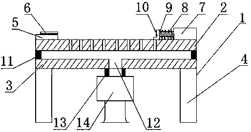
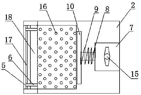
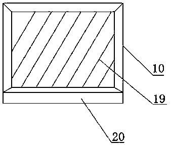
[0017] see figure 1 , figure 2 and image 3 , the present invention provides a technical solution: a jig for circuit board processing, including a clamp body 1, a loading plate 2 and a bottom plate 3 are fixedly installed above the clamp body 1, and the loading plate 2 is arranged on the bottom of the bottom plate 3 Directly above, the support column 4 is fixedly installed under the clamp body 1, and the two sides of the upper surface of the loading plate 2 are respectively fixedly installed with a limit baffle 5 and a fixed seat 7, and on the limit baffle 5 A sliding limit block 6, a sliding groove 17 and a card groove 18 are provided, the sliding limiting block 6 is fixed on the sliding groove 17, and the left side of the fixing seat 7 is fixedly equipped with a telescopic rod 8 and a compression spring 9, and The compression spring 9 is sleeved on the telescopic rod 8, one end of the telescopic rod 8 is fixedly installed with a top plate 10, the bottom of the top plate 1...


PUM


Abstract

The invention discloses a fixture for machining of a circuit board. The fixture comprises a fixture body. A loading plate and a bottom plate are fixedly mounted on the upper portion of the fixture body. Supporting columns are fixedly mounted on the lower portion of the fixture body. A limiting baffle and a fixed seat are fixedly mounted on the two sides of the upper surface of the loading plate. The limiting baffle is provided with a sliding limiting block, a sliding groove and a clamping groove. The sliding limiting block is fixed to the sliding groove. A telescopic rod and a compression spring are fixedly mounted on the left side of the fixed seat. A top plate is fixedly mounted at one end of the telescopic rod. A plurality of penetrating holes are further formed in the loading plate. Acavity is formed between the bottom plate and the loading plate. An air pumping hole is formed in the center of the bottom plate. According to the fixture for machining of the circuit board, through the limiting baffle and the movable top plate, clamping of the circuit board is more stable; and through arrangement of the multiple penetrating holes and a vacuum machine, the circuit board cannot fall off suddenly in the clamping process, the safety of workers is ensured, and meanwhile, accidental damage of the circuit board is further prevented.

Description

technical field [0001] The invention relates to the technical field of circuit board processing, in particular to a fixture for circuit board processing. Background technique [0002] With the rapid development of electronic products, people's demand for electronic products is also increasing. In the production process of electronic products, the main technology lies in the processing of circuit boards. In the process of processing circuit boards, sometimes due to The problem of fixtures makes many mistakes in the process of circuit board processing, which brings unnecessary waste and certain economic losses. At present, the existing fixtures are all aimed at a certain type of circuit board processing, or shape The size is fixed and not universal. For example, the Chinese patent No. CN 201039592 Y is used to fix the circuit board whose edge is to be removed. The action of bending the edge will not cause damage to the circuit board, but its The function is single, and the sh...

Claims


Application Information

Patent Timeline
Patent Type & Authority Applications(China)
IPC IPC(8): B25B11/00
CPCB25B11/005
Inventor 郑晓滨
Owner 广东高旗技术有限公司
Learn More