
Water ring particle cutting machine

A granulator and water ring technology, applied in the field of waste plastic granulation, can solve the problems of inconsistent water pressure, easy splashing, temperature drop on the die surface, etc., and achieve the effects of preventing mechanical damage, saving water resources, and facilitating drying.

Pending Publication Date: 2018-07-03
ZHANGJIAGANG GRACE MACHINERY CO LTD
View PDF9 Cites 0 Cited by
  • Summary
  • Abstract
  • Description
  • Claims
  • Application Information

AI Technical Summary

Problems solved by technology

In the ordinary water ring pelletizing process, the high-pressure water flow enters the water chamber, and the water flows out through the gap on one side of the water chamber to cool the plastic particles and take them out of the water ring shell. The disadvantage of this water ring is that the water ring has various The water pressure at the upper part is inconsistent, the water outlet pressure at the upper part is relatively small, and it is not easy to form a stable rotating water ring, and the cooling water is easy to splash, causing the temperature of the mold surface to drop, and it may also cause the mold surface to be blocked or even blocked. The water ring will take the cut plastic particles out through the water flow, and then dry the plastic to dehydrate. When it is dry, there will be a lot of water on the surface of the plastic, which will prolong the drying and dehydration time, and even lead to poor drying and dehydration effect.

Method used


Image

  • Water ring particle cutting machine
  • Water ring particle cutting machine

Examples


Embodiment Construction

[0022] In order to make the technical means, creative features, goals and effects achieved by the present invention easy to understand, the present invention will be further described below in conjunction with specific embodiments.

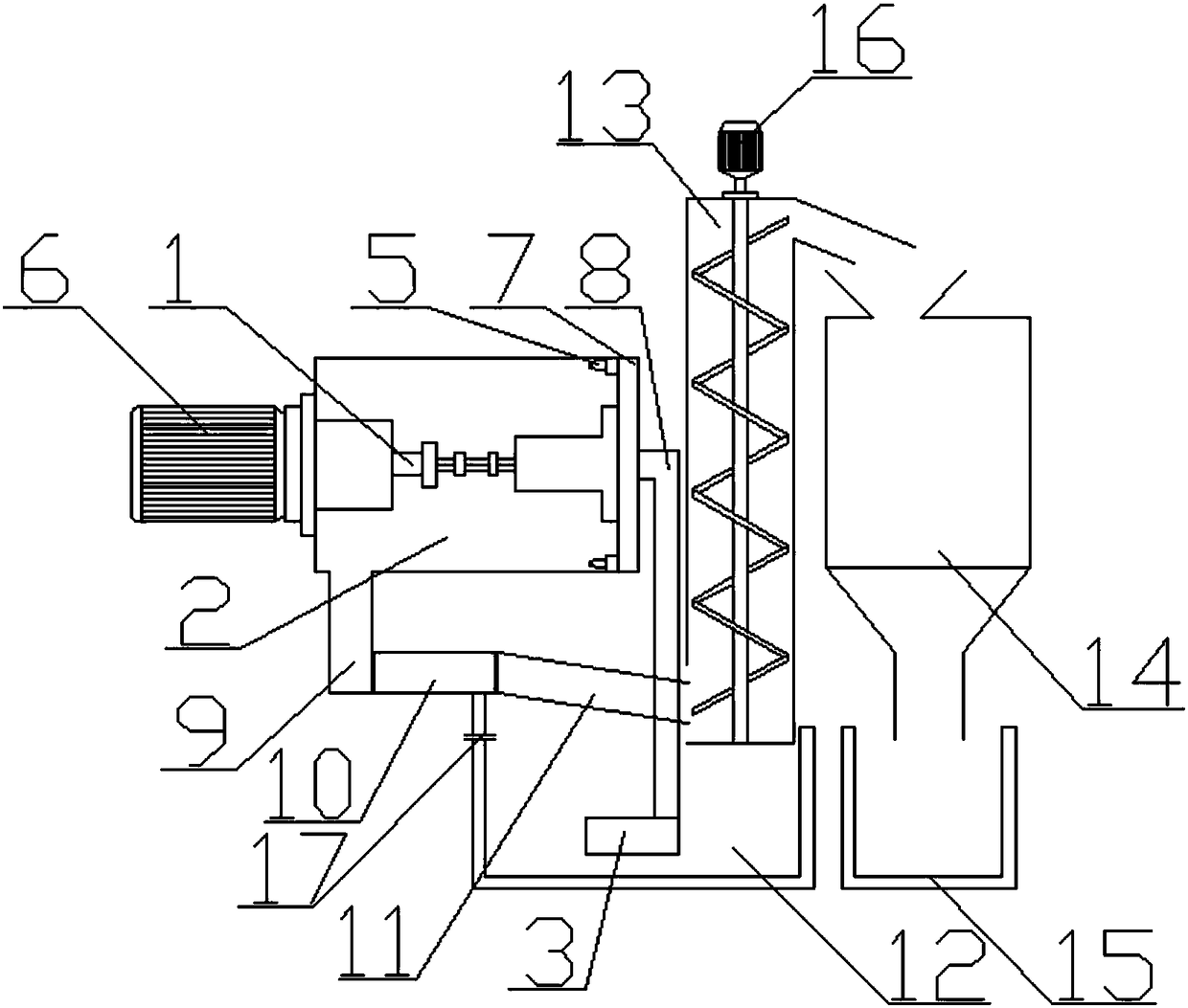
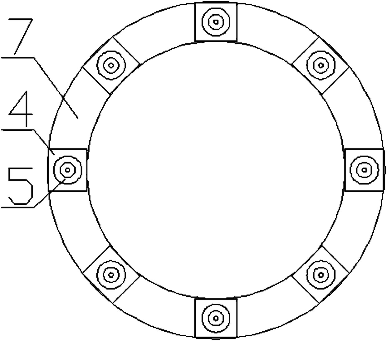
[0023] according to figure 1 and figure 2 A kind of water ring granulator shown, comprises granulator 1, water ring shell 2, water pump 3, plenum chamber 4 and nozzle 5, and described water ring shell 2 is horizontal cylindrical, and described granulator 1 is located inside the water ring shell 2, the granulation device 1 is connected to the center of both sides of the water ring shell 2, a motor 6 is provided on the left side of the water ring shell 2, and the motor 6 is connected to the granulation device 1, so The right side of the water ring shell 2 is provided with a communication chamber 7, the communication chamber 7 is in the shape of a ring, the right side of the communication chamber 7 is connected to the water pipe 8, the water pipe 8...


PUM


Abstract

The invention puts forward a water ring particle cutting machine, and relates to the technical field of waste plastic particle generation. The water ring particle cutting machine comprises a particlecutting device and a water ring shell, the particle cutting device is connected with the two sides of the interior of the water ring shell, the right side of the interior of the water ring shell is provided with a communication chamber, the right side of the communication chamber is connected with a water pipe, and the water pipe is connected with a water pump. The left side of the communication chamber is connected with multiple pressure stabilization chambers, the left side of each pressure stabilization chamber is connected with a nozzle, the lower side of the left side of the water ring shell is connected with a water receiving tank, the lower side of the water receiving tank is connected with a flowing tank, the right of the flowing tank is connected with a filtering tank, a water accumulation box is arranged below the filtering tank, and the water pump is arranged in the water accumulation box. The pressure stabilization chambers are arranged on the right sides of the nozzles, itis guaranteed that the water pressures of all the nozzles are identical, cooling water sprayed from the nozzles forms a water ring, the problem that the cooling water easily splashes due to differentpressures of all the nozzles is avoided, the cooling water with plastic particles is filtered twice, the filtered water is collected for the water pump providing a water source for the nozzles, the cooling water is recycled, and more water is saved.

Description

technical field [0001] The invention relates to the technical field of waste plastic granulation, in particular to a water ring granulator. Background technique [0002] In the waste plastic recycling industry, due to the high viscosity of polyolefin plastics, the water ring granulation process is generally used for its recycling. The material is finally extruded from the die surface and cut by the rotating blade to become small-sized particles. The hot particles fall into the water flow generated by the water ring, and the particles are cooled and shaped, and then dehydrated, vibrated and sorted. Heavy packaging, eventually turned into finished plastic particles. In the ordinary water ring granulation process, the high-pressure water flow enters the water chamber, and the water flows out through the gap on one side of the water chamber to cool the plastic particles and take them out of the water ring shell. The disadvantage of this water ring is that the water ring has var...

Claims


Application Information

Patent Timeline
IPC IPC(8): B29B9/06B29B9/16
CPCB29B9/065B29B9/16
Inventor 严栋
Owner ZHANGJIAGANG GRACE MACHINERY CO LTD
Learn More