
Car brake pedal arm

A car brake and pedal arm technology, applied in the field of auto parts, can solve the problems of high noise, inability to manufacture large bends, and large plate thickness, etc., to achieve the effect of optimizing car space, improving strength, and increasing bending degree

Pending Publication Date: 2018-07-03
重庆鹏得基业汽车部件有限公司
View PDF0 Cites 0 Cited by
  • Summary
  • Abstract
  • Description
  • Claims
  • Application Information

AI Technical Summary

Problems solved by technology

The disadvantages of this kind of pedal arm are: the thickness of the plate is relatively large, and the selection of materials is limited. Generally, only conventional Q235 and other series materials can be used, and the stamping equipment used in the manufacture is large and noisy; in addition, the pedal arm is more bent. The larger the strength, the lower the strength. In order to ensure the strength, it is impossible to make large bends, which limits the design of the body

Method used


Image

  • Car brake pedal arm
  • Car brake pedal arm
  • Car brake pedal arm

Examples


Embodiment Construction

[0019] Embodiments of the technical solutions of the present invention will be described in detail below in conjunction with the accompanying drawings. The following examples are only used to illustrate the technical solutions of the present invention more clearly, and therefore are only examples, rather than limiting the protection scope of the present invention.

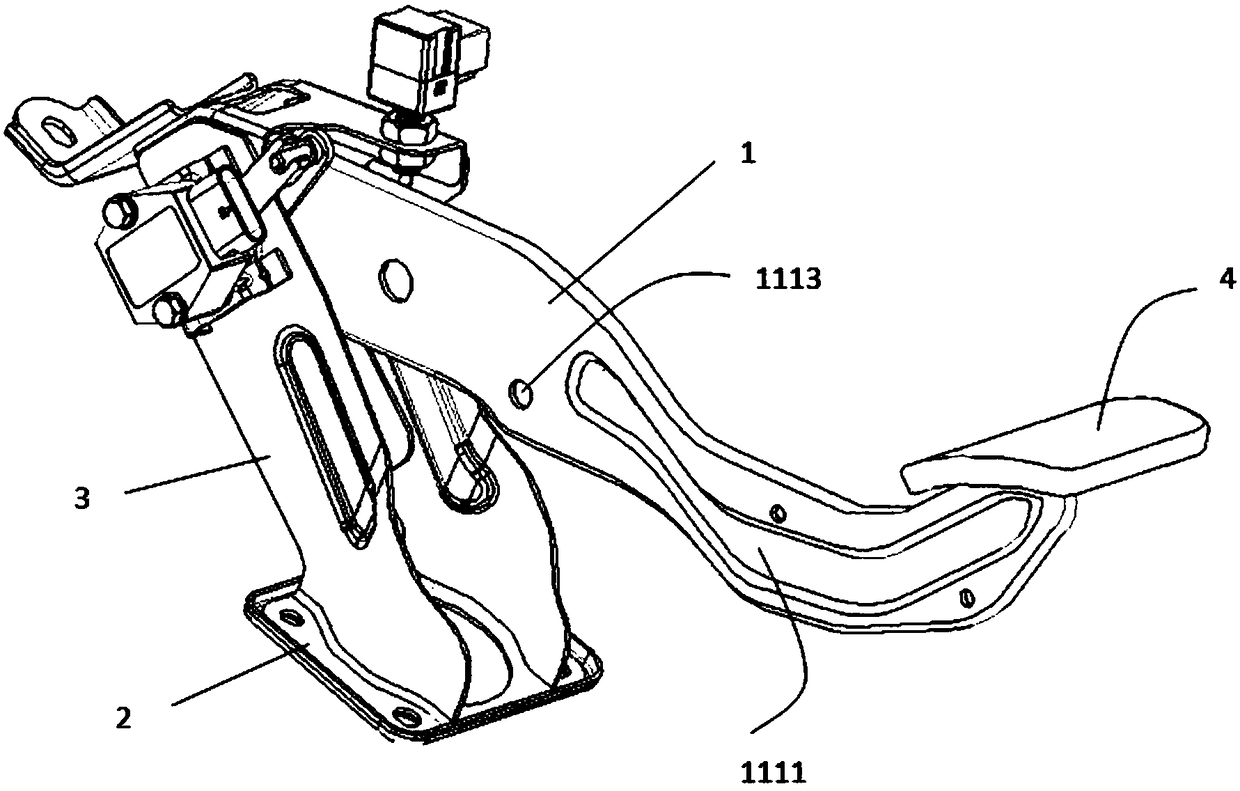
[0020] Such as figure 2 The automobile brake pedal mechanism shown includes a fixed plate 2, a bracket 3 fixedly arranged on the fixed plate 2, and a pedal arm 1 rotatably connected to the bracket, and a pedal sheet 4 is welded at the tail of the pedal arm.

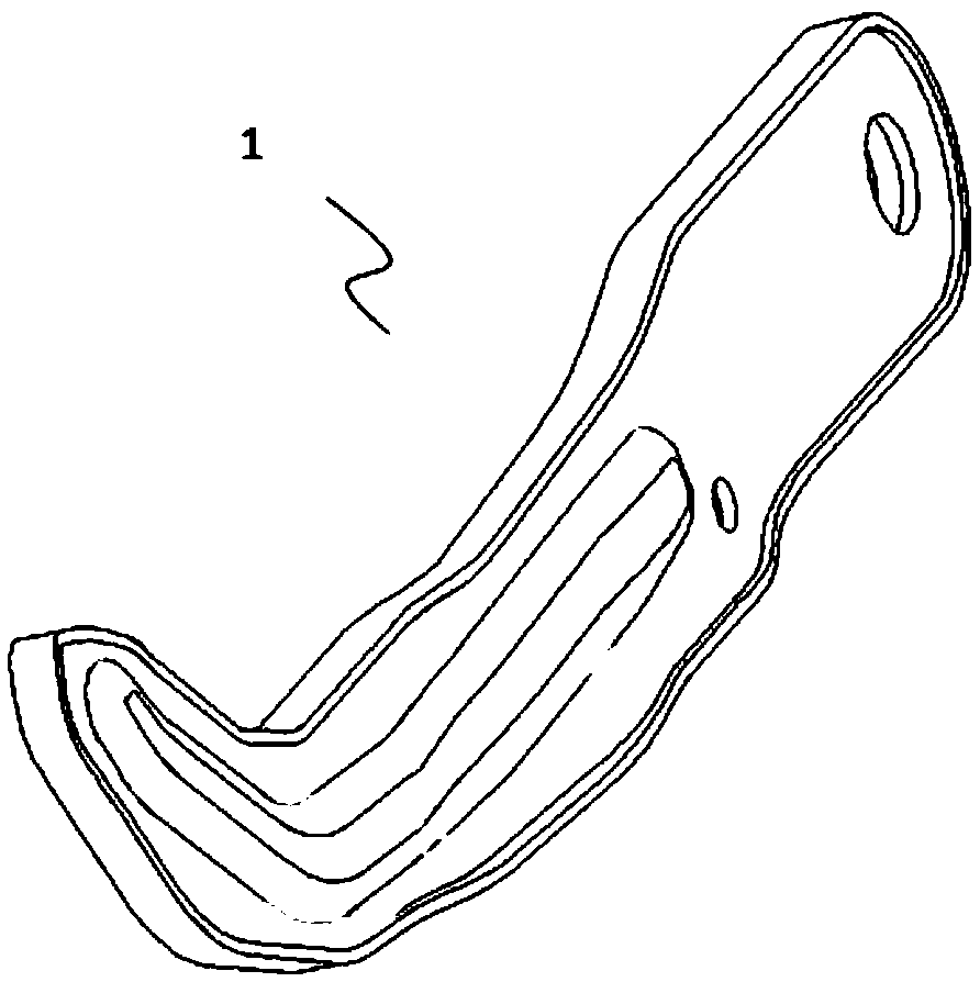
[0021] Such as Figure 3 to Figure 5 The shown automobile brake pedal arm 1 includes a pedal arm body 11, the pedal arm body includes a base plate 111 and a flange 112 arranged on the edge of the base plate, the base plate and the flange form a cavity, and the cavity is set There is a reinforcing plate 12 whose shape is adapted to the shape of the bottom pl...


PUM


Abstract

The invention provides a car brake pedal arm which comprises a pedal arm body. The pedal arm body comprises a bottom plate and a flange arranged at the edge of the bottom plate. A cavity is formed bythe bottom plate and the flange and internally provided with a reinforcing plate. The reinforcing plate is matched with the bottom plate in shape. According to the car brake pedal arm, the structure is simple, the strength of the car brake pedal arm is greatly improved, and the car space is optimized.

Description

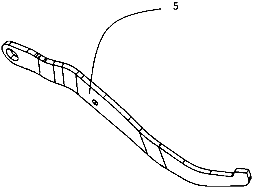
technical field [0001] The invention relates to an automobile part, in particular to an automobile brake pedal arm. Background technique [0002] The automobile brake pedal arm is a key component in the automobile brake pedal system, and its safety performance cannot be ignored. Such as figure 1 As shown, most of the brake pedal arms 5 of automobiles currently on the market are manufactured by plate forming, and in order to meet the strength requirements, a plate with a thickness of 8mm is usually selected for processing and forming. The disadvantages of this kind of pedal arm are: the thickness of the plate is relatively large, and the selection of materials is limited. Generally, only conventional Q235 and other series materials can be used, and the stamping equipment used in the manufacture is large and noisy; in addition, the pedal arm is more bent. The larger the strength, the lower the strength. In order to ensure the strength, it is impossible to make large bends,...

Claims


Application Information

Patent Timeline
Patent Type & Authority Applications(China)
IPC IPC(8): B60T7/06
CPCB60T7/06
Inventor 王跃鹏颜久余陈家林
Owner 重庆鹏得基业汽车部件有限公司
Learn More