
Centralized mounting bracket for avionics equipment

A technology for avionics equipment and mounting brackets, which is applied to the structural parts of electrical equipment, electrical components, transportation and packaging, etc. It can solve the problems of reducing the laying and fixing of communication cables on the aircraft, reducing the load of the aircraft, and cumbersome operations, etc., to improve signal transmission Reliability, reduce the vibration level of the system, and improve the effect of working reliability

Inactive Publication Date: 2018-07-03
LUOYANG INST OF ELECTRO OPTICAL EQUIP OF AVIC
View PDF6 Cites 7 Cited by
  • Summary
  • Abstract
  • Description
  • Claims
  • Application Information

AI Technical Summary

Problems solved by technology

The existing single mounting bracket for avionics equipment cannot realize the centralized installation of multiple avionics equipment. In contrast, the centralized mounting bracket can reduce the laying and fixing of communication cables on the aircraft and reduce the load of the aircraft. Most of the existing mounting brackets use swing Bolts and fastening hooks fix the avionics equipment, and the operation is cumbersome and cannot be quickly loaded and unloaded, which cannot meet the requirements of use. There is an urgent need for avionics equipment with centralized and fast loading and unloading, vibration reduction, ventilation and heat dissipation, and can realize the connection between the equipment room and the system and the aircraft. Mounting bracket for multiple functions of communication link

Method used


Image

  • Centralized mounting bracket for avionics equipment
  • Centralized mounting bracket for avionics equipment
  • Centralized mounting bracket for avionics equipment

Examples


Embodiment Construction

[0029] Embodiments of the present invention are described in detail below, examples of which are shown in the drawings, wherein the same or similar reference numerals designate the same or similar elements or elements having the same or similar functions throughout. The embodiments described below by referring to the figures are exemplary and are intended to explain the present invention and should not be construed as limiting the present invention.

[0030] In describing the present invention, it should be understood that the terms "center", "longitudinal", "transverse", "length", "width", "thickness", "upper", "lower", "front", " Orientation indicated by rear, left, right, vertical, horizontal, top, bottom, inside, outside, clockwise, counterclockwise, etc. The positional relationship is based on the orientation or positional relationship shown in the drawings, which is only for the convenience of describing the present invention and simplifying the description, rather than ...


PUM


Abstract

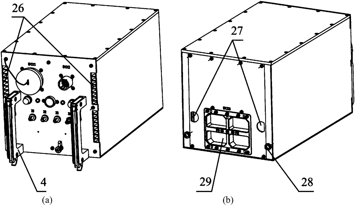
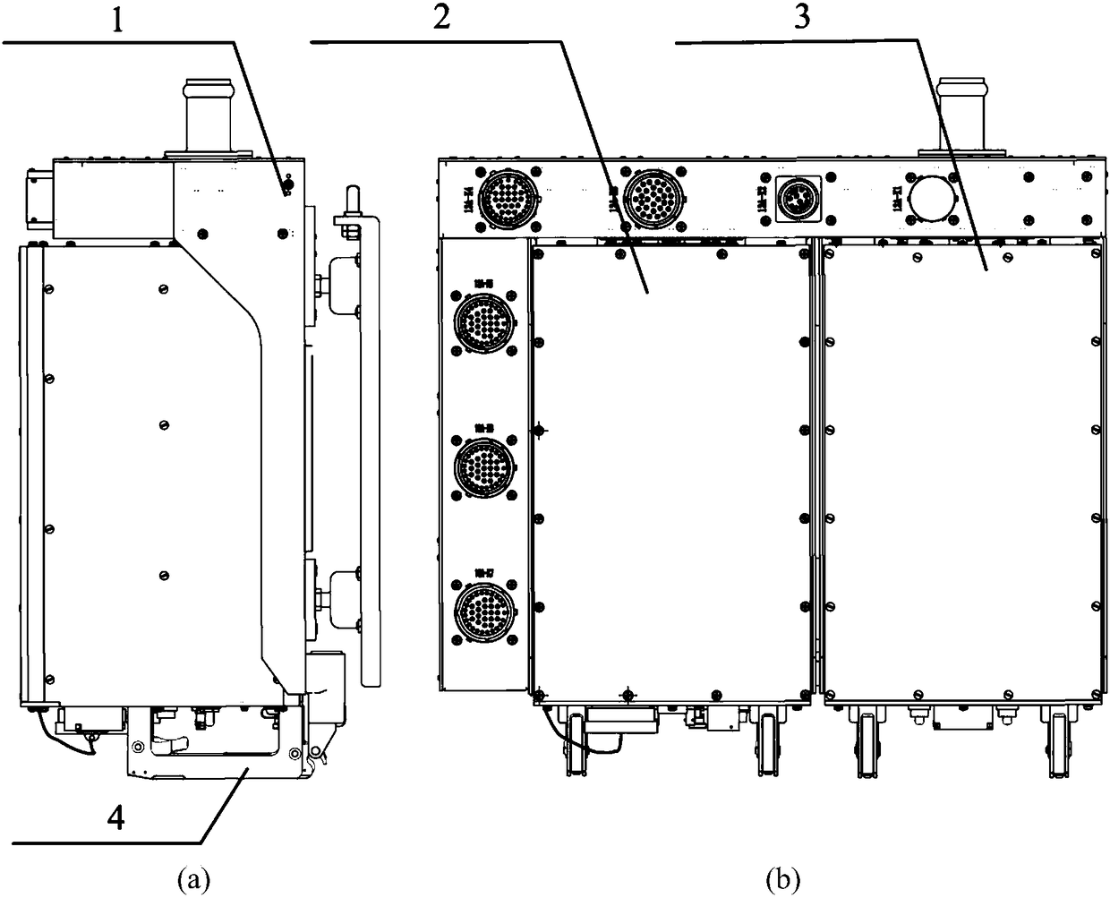
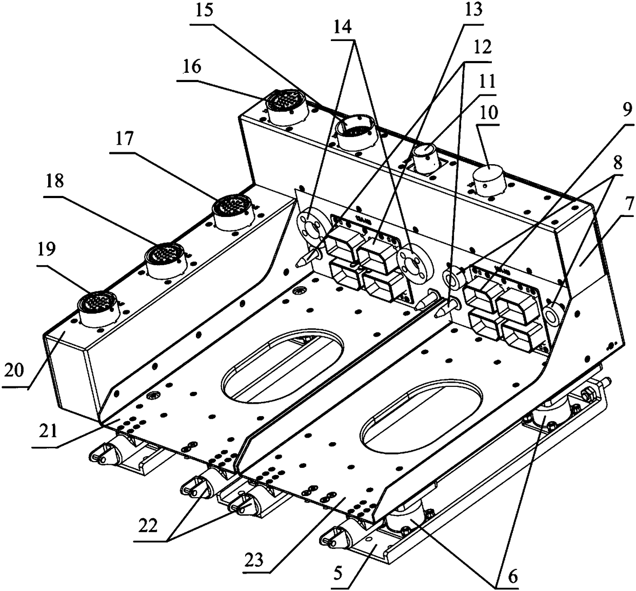
The invention provides a centralized mounting bracket for avionics equipment. Centralized and fast loading and unloading of multiple avionics equipment can be achieved. The centralized mounting bracket includes a fast loading and unloading mechanism, a damping mechanism, a ventilating and cooling pipeline, and a communication channel for communication between equipment as well as between a systemand an aircraft. The fast loading and unloading mechanism comprises fasteners and spring positioning pins which are arranged on the centralized mounting bracket, and a locking handle on the avionics equipment. The damping system consists of six dampers, the vibration magnitude of the avionics equipment can be effectively decreased, and the reliability of the system is improved. The ventilating andcooling pipeline includes an air inlet pipe, an air cavity, a ventilating pipe and a sealing ring and can provide air cooling conditions for the avionics equipment, the working temperature of internal electronic components can be effectively adjusted, and the working reliability is improved. The communication channel for communication between equipment as well as between the system and the aircraft comprises circular connectors mounted on a back shell and a left shell of the centralized mounting bracket and a rectangular connector mounted on a front cover plate, and communication connection between equipment as well as between the system and the aircraft is achieved.

Description

technical field [0001] The invention belongs to the field of mechanical structure design, and proposes a centralized mounting bracket for avionics equipment to meet the needs of centralized and fast loading and unloading, vibration reduction, ventilation and heat dissipation, and communication connection between the avionics equipment on board. Background technique [0002] Avionics equipment needs to be quickly installed and disassembled during use and maintenance, and internal electronic components must withstand various vibration loads, shocks and thermal shocks. The existing single mounting bracket for avionics equipment cannot realize the centralized installation of multiple avionics equipment. In contrast, the centralized mounting bracket can reduce the laying and fixing of communication cables on the aircraft and reduce the load of the aircraft. Most of the existing mounting brackets use swing Bolts and fastening hooks fix the avionics equipment, and the operation is ...

Claims


Application Information

Patent Timeline
Patent Type & Authority Applications(China)
IPC IPC(8): B64D47/00F16F15/04H05K7/20
CPCB64D47/00F16F15/04H05K7/20863
Inventor 张松鹏张红钰周海亮杨会杰王恒玉
Owner LUOYANG INST OF ELECTRO OPTICAL EQUIP OF AVIC
Learn More