Method for designing optical system as oblique camera lens

一种光学系统、设计方法的技术,应用在光学、光学元件、仪器等方向,能够解决照片分辨率不均匀等问题,达到控制因素少、容易设计的效果

Active Publication Date: 2018-07-03
TSINGHUA UNIV +1
View PDF4 Cites 13 Cited by
  • Summary
  • Abstract
  • Description
  • Claims
  • Application Information

AI Technical Summary

Problems solved by technology

For the camera, there is a large difference in the object distance between point A and point B, and the object distance at point B is greater than that at point A. Therefore, in the obtained photo, the resolution of point A is higher than that of point B, and the resolution of the photo is uneven

Method used


Image

  • Method for designing optical system as oblique camera lens
  • Method for designing optical system as oblique camera lens
  • Method for designing optical system as oblique camera lens

Examples


Embodiment Construction

[0034] The optical system used as a squint camera lens provided by the present invention will be further described in detail below in conjunction with the accompanying drawings and specific embodiments.

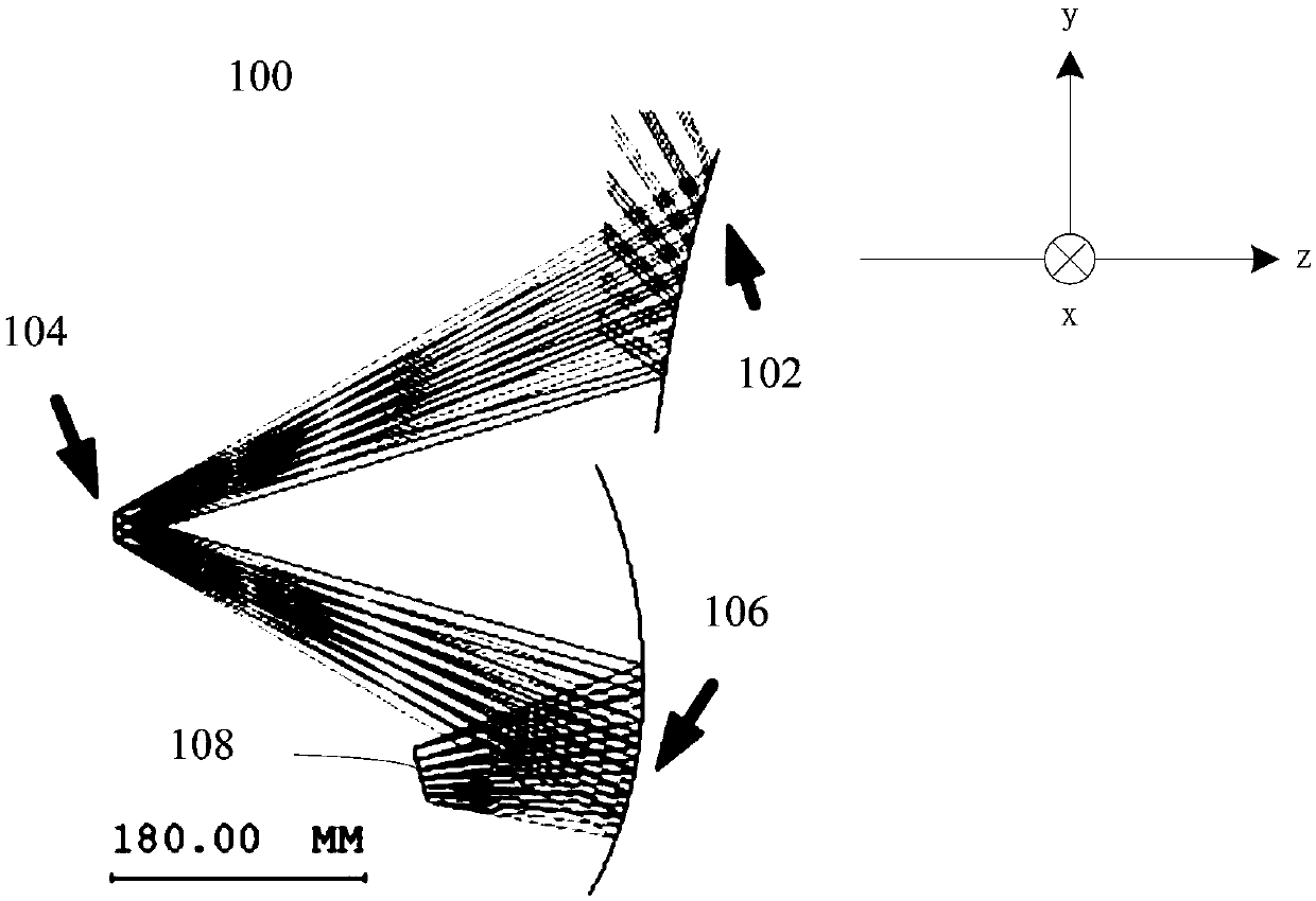
[0035] see figure 2 , the present invention provides an optical system 100 used as a squint camera lens, including: a primary reflector 102 , a primary reflector 104 , a third reflector 106 , and an image sensor 108 . The secondary reflector 104 is located on the reflection optical path of the main reflector 102 , the third reflector 106 is located on the reflection optical path of the secondary reflector 104 , and the image sensor 108 is located on the reflection optical path of the third reflector 106 . The reflective surfaces of the primary reflector 102 and the third reflector 106 are free-form surfaces, and the reflective surface of the secondary reflector 104 is a spherical surface. The reflective surface of the secondary reflector 104 is an aperture surface.

[0036...


PUM


Abstract

The invention relates to a method for designing an optical system as an oblique camera lens. The method comprises: an initial system consisting of an primary initial mirror, an initial secondary mirror, and an initial third mirror is established; a new object-image relationship is established, a plurality of first characteristic light rays are selected, the plurality of first characteristic lightrays are tracked forwardly from object space to an image sensor, a plurality of characteristic data points of a to-be-calculated third reflector are calculated based on the plurality of first characteristic light rays and the new object-image relationship while the primary initial mirror and the initial secondary mirror are kept to be unchanged, and curved-surface fitting is carried out on the plurality of characteristic data points to obtain a third reflector; and a plurality of view fields and a plurality of second characteristic light rays are selected, the plurality of second characteristic light rays are tracked to the object space reversely from the image sensor, a plurality of second characteristic data points of a to-be-calculated primary reflector are calculated based on the plurality of second characteristic light rays and the new object-image relationship, and curved-surface fitting is carried out on the plurality of second characteristic data points to obtain a primary reflector.

Description

technical field [0001] The invention relates to the field of imaging system design, in particular to a design method of an optical system used as a squint camera lens. Background technique [0002] A common imaging system, such as a camera, takes pictures while looking squarely at the observed target. However, in some special fields, such as observing the ground with obstacles at high altitude, the camera cannot observe the area to be observed when it is directly above the area to be observed, which requires a special imaging system, that is, the imaging system of the squint camera. See figure 1 , the area between A and B is the area to be observed, and the observation point is point C. The angle between the field of view at point A and the vertical line passing through point C is called the tilt angle. For the camera, there is a large difference in the object distance between point A and point B, and the object distance at point B is greater than that at point A. Therefo...

Claims


Application Information

Patent Timeline
Patent Type & Authority Applications(China)
IPC IPC(8): G02B27/00G02B17/06
CPCG02B17/06G02B27/0012G02B17/0642
Inventor 侯威朱钧金国藩范守善
Owner TSINGHUA UNIV
Why Eureka
Try Eureka