Wavelength tunable interference filter, optical filter device, optical module, and electronic apparatus

a technology of tunable interference and filter, applied in the field ofwavelength tunable interference filter, optical filter device, optical module, electronic apparatus, can solve the problem of uneven resolution and achieve the effect of uniform resolution and accurately performing various kinds of processing

Inactive Publication Date: 2014-04-03
SEIKO EPSON CORP
View PDF5 Cites 5 Cited by
  • Summary
  • Abstract
  • Description
  • Claims
  • Application Information

AI Technical Summary

Benefits of technology

[0035]In the electronic apparatus described above, similar to the wavelength tunable interference filter, the optical filter device, and the optical module described above, it is possible to extract light having each wavelength in the measurement wavelength range with uniform resolution. Therefore, the electronic apparatus can accurately perform various kinds of processing using light with each wavelength extracted with uniform resolution.

Problems solved by technology

In practice, however, if the diaphragm is bent, the protruding portion is also slightly bent, and the movable mirror provided in the protruding portion is also bent.
Accordingly, when the light extracted by the wavelength tunable interference filter is shifted from the long wavelength side to the short wavelength side as described above, there is a problem in that the resolution becomes more uneven due to the influence of the bending of the movable mirror and the influence of the reflectance characteristics of the fixed mirror or the movable mirror.

Method used


Image

  • Wavelength tunable interference filter, optical filter device, optical module, and electronic apparatus
  • Wavelength tunable interference filter, optical filter device, optical module, and electronic apparatus
  • Wavelength tunable interference filter, optical filter device, optical module, and electronic apparatus

Examples


first embodiment

[0054]Hereinafter, a first embodiment of the invention will be described with reference to the accompanying drawings.

Configuration of a Spectrometer

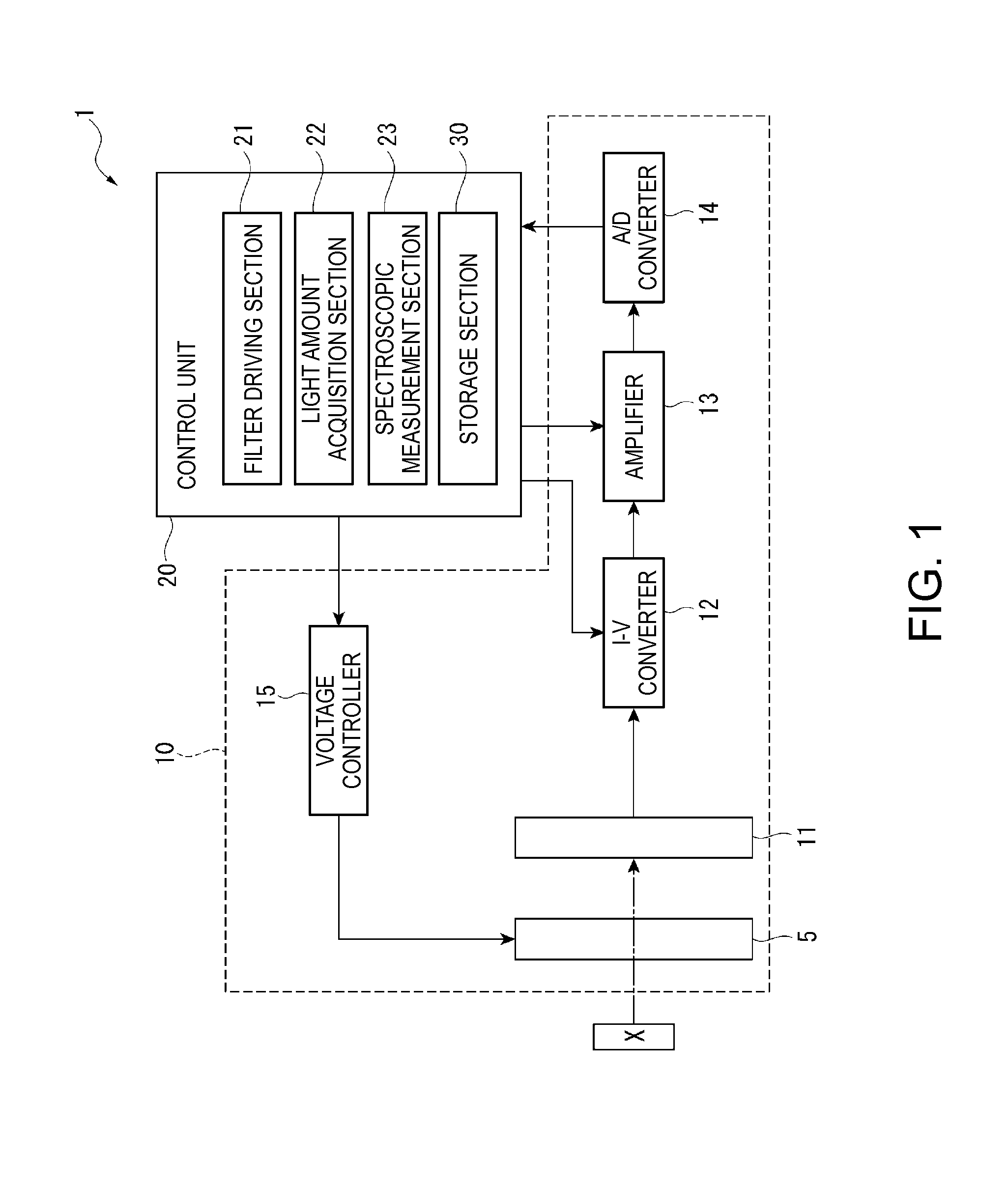
[0055]FIG. 1 is a block diagram showing the schematic configuration of a spectrometer according to the first embodiment of the invention.

[0056]A spectrometer 1 is an electronic apparatus according to the embodiment of the invention, and is an apparatus that measures a spectrum of measurement target light reflected by a measurement target X on the basis of the measurement target light. In addition, in the present embodiment, the example is shown in which the measurement target light reflected by the measurement target X is measured. However, for example, when a light emitter such as a liquid crystal panel is used as the measurement target X, light emitted from the light emitter may also be used as the measurement target light.

[0057]As shown in FIG. 1, the spectrometer 1 includes an optical module 10 and a control unit 20.

Configuration of ...

second embodiment

[0129]Next, a second embodiment of the invention will be described below.

[0130]In the first embodiment described above, the configuration in which the curve forming film 57 is provided on the outer surface 521B of the movable portion 521 has been illustrated. On the other hand, the second embodiment is different from the first embodiment in that the curve forming film is provided on the movable surface 521A side of the movable portion 521.

[0131]FIG. 9 is a cross-sectional view showing the schematic configuration of a wavelength tunable interference filter 5A of the second embodiment. In addition, in explaining the subsequent embodiments, the same components as in the first embodiment are denoted by the same reference numerals, and explanation thereof will be omitted or simplified.

[0132]As shown in FIG. 9, in the present embodiment, a curve forming film 57A is formed so as to cover the movable reflective film 55 provided in the movable portion 521.

[0133]In this case, a film having a ...

third embodiment

[0136]Next, a third embodiment of the invention will be described below.

[0137]In the second embodiment described above, the configuration in which the surface of the movable reflective film 55 is covered by the curve forming film 57A has been illustrated. On the other hand, the third embodiment is different from the second embodiment in that the curve forming film is provided between the movable substrate 52 and the movable reflective film 55.

[0138]FIG. 10 is a cross-sectional view showing the schematic configuration of a wavelength tunable interference filter 5B of the third embodiment.

[0139]As shown in FIG. 10, in the present embodiment, a curve forming film 57B is provided on the movable surface 521A of the movable portion 521, and the movable reflective film 55 is provided on the curve forming film 57B.

[0140]In this case, a film having a tensile stress is used as the curve forming film 57B as in the second embodiment. In this manner, it is possible to curve the movable substrate...


PUM


Abstract

A wavelength tunable interference filter, an optical filter device, an optical module, and an electronic apparatus include a fixed substrate, a movable substrate, a fixed reflective film provided on the fixed substrate, a movable reflective film provided on the movable substrate and facing the fixed reflective film with an inter-reflective film gap interposed therebetween, and an electrostatic actuator that changes the size of the inter-reflective film gap. The movable substrate is curved in a convex shape in a direction away from the fixed substrate in an initial state. The reflective film has reflectance characteristics in which the first reflectance at a predetermined first wavelength in a measurement wavelength range is lower than the second reflectance at a second wavelength longer than the first wavelength.

Description

BACKGROUND[0001]1. Technical Field[0002]The present invention relates to a wavelength tunable interference filter, an optical filter device, an optical module, and an electronic apparatus.[0003]2. Related Art[0004]A wavelength tunable interference filter that extracts light with a predetermined wavelength from incident light is known (for example, refer to JP-A-2003-185941).[0005]The Fabry-Perot filter (wavelength tunable interference filter) disclosed in JP-A-2003-185941 includes a fixed substrate and a movable substrate disposed opposite the fixed substrate with a spacer interposed therebetween, and a fixed mirror is provided on the fixed substrate and a movable mirror is provided on the movable substrate. In addition, the movable substrate includes a diaphragm and a protruding portion surrounded by the diaphragm, and the movable mirror is disposed in the protruding portion. In addition, in the wavelength tunable interference filter, a configuration is adopted in which the size of...

Claims


Application Information

Patent Timeline
Patent Type & Authority Applications(United States)
IPC IPC(8): G02B5/28
CPCG02B5/28G02B26/001
Inventor NISHIMURA, TERUYUKIKOMATSU, HIROSHI
Owner SEIKO EPSON CORP
Why Eureka
Try Eureka