Thrombus extraction scaffold

A technology of metal ribs and push rods, applied in the field of medical devices, can solve the problems of difficult operation, large damage to blood vessel walls, and easy to cause various concurrent inflammations, etc.

Pending Publication Date: 2018-07-06
ENEIDE MEDICAL TECH SHANGHAI CO LTD
View PDF7 Cites 4 Cited by
  • Summary
  • Abstract
  • Description
  • Claims
  • Application Information

AI Technical Summary

Problems solved by technology

Mechanical thrombectomy includes the following methods: thrombectomy, which is a more thorough method of thrombectomy, but causes too much damage to the vessel wall, and can easily cause various concurrent inflammations; laser thrombectomy, which is difficult to operate, and the laser energy If the energy is too low, it will be ineffective, if the energy is too high, it will damage the blood vessel, and it will also easily cau...

Method used


Image

  • Thrombus extraction scaffold
  • Thrombus extraction scaffold
  • Thrombus extraction scaffold

Examples


Embodiment 1

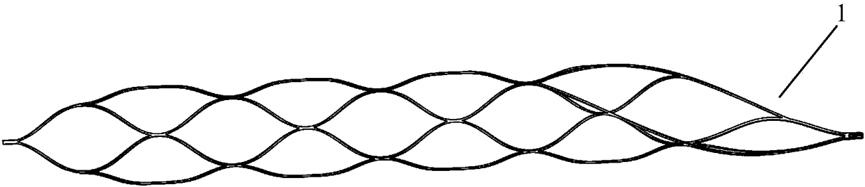
[0165] The thrombectomy bracket of this embodiment is as Image 6 As shown, it includes stent 1 and push rod 3, which are mainly used to remove intracranial thrombus.

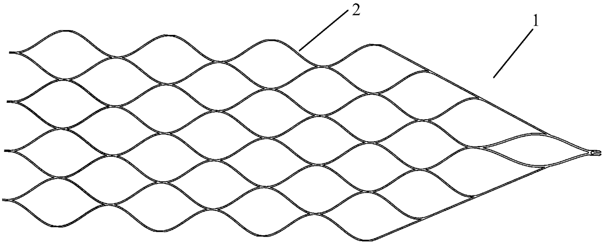
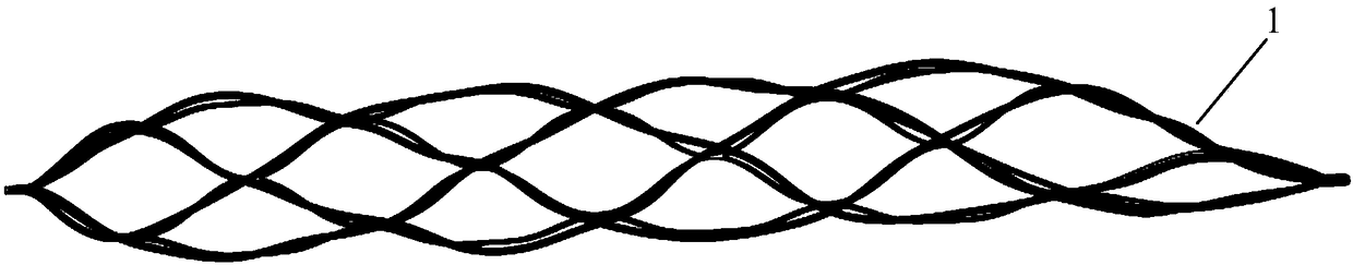
[0166] The stent 1 is cut from a metal tube, and the cut metal tube is in the shape of a plurality of metal ribs 2 helically intersecting. The metal ribs 2 gather at the far end of the stent 1 to the first gathering point (gathered and melted Polymer material film wrapping). The distal end of the stent 1 is folded into a closed shape, so that the ability of the stent to capture thrombus is stronger, and a polymer tube (material can be but not limited to pebax, nylon, TPU) is used to integrate the heat-shrinkable part of the folded head into one. The proximal end of the stent 1 is obliquely cut, and the metal ribs 2 converge at the proximal end of the stent 1 to form a second gathering point. The distal opening of such a stent 1 is a small opening, and the shrunk stent 1 is small in size, and is easier to ente...

Embodiment 2

[0176] The thrombectomy bracket of this embodiment is the same as that of Example 1, the difference is that the number of developing wires of the thrombectomy bracket of this embodiment is the same as the number of strands of the ribs at the distal end of the bracket, both of which are 8. A developing wire is independently attached to a strand of metal ribs, and one end of the developing wire is positioned and connected to the far end of the stent, and the other end of the developing wire is positioned and connected to the proximal end of the stent, and the developing wire can also develop the shape of the entire stent .

Embodiment 3

[0178] The thrombectomy bracket of this embodiment is the same as that of Example 1, and the difference is that the number of developing wires in the thrombectomy bracket of this embodiment is 4, and the number of strands of the ribs at the far end of the bracket is 8 strands, that is, one developing wire Attached to two strands of metal ribs, this reduces the number of developing wires. The winding method is as follows: a developing wire is wound from the far end of the stent to the proximal end of the stent along the metal rib, and returns to the far end of the stent through the notch.


PUM

PropertyMeasurementUnit
Outer diameteraaaaaaaaaa
Lengthaaaaaaaaaa

Abstract

The invention discloses a thrombus extraction scaffold. Specifically, the thrombus extraction scaffold comprises a scaffold body and a push rod; the scaffold body is formed by cutting a metal tube, and the cut metal tube is in a shape of helical crossing of a plurality of strands of metal ribs; the metal ribs are gathered to form a first gathering point at the far end of the scaffold body, the near end of the scaffold body is in a diagonal shape, and the metal ribs are gathered to form a second gathering point at the near end of the scaffold body; developing wires are attached to any strand ofthe metal ribs, and the developing wires are attached to the metal ribs; a notch is formed in the second gathering point, the far end of the push rod is provided with an insert matched with the notch, the notch and the insert are assembled and fixed through embedding, and the scaffold body and the push rod are connected to form a whole. The thrombus extraction scaffold is used for mechanically extracting thrombi blocking intracranial vessels when acute ischemic stroke of a patient happens, so that the treatment purposes of revascularization and blood flow recovery are achieved.

Description

technical field [0001] The invention relates to the field of medical instruments, and more particularly relates to a thrombectomy bracket. Background technique [0002] Intravascular thrombosis is a common and frequently-occurring disease in clinical practice, and intracranial thrombosis is the most important. It causes cerebral embolism and has the characteristics of high morbidity, disability, mortality and recurrence. Major diseases causing death and disability in middle-aged and elderly people. With the continuous increase of the elderly population and the improvement of living standards, the incidence of cerebrovascular disease is constantly increasing. According to the survey, there are currently 3 million new cerebral thrombosis groups in my country every year, and the proportion of acute cerebral thrombosis in stroke has also increased from 55.8% to 81.6%, becoming the number one brain disease. [0003] "Cerebral stroke" is also called "stroke" or "cerebrovascular ...

Claims


Application Information

Patent Timeline
IPC IPC(8): A61B17/221A61F2/91A61F2/966
CPCA61B17/221A61B2017/00778A61B2017/22038A61B2017/2212A61F2/91A61F2/966A61F2220/0058A61F2250/0098
Inventor 朱大伟沈碧峰付亮辉
Owner ENEIDE MEDICAL TECH SHANGHAI CO LTD
Why Eureka
Try Eureka