Suffocation type movable tunnel fire extinguishing device

A fire-extinguishing device and tunnel technology, applied in fire rescue, medical science, dentistry, etc., can solve the problems of serious economic burden, difficult to reach rescue in time, long and narrow tunnel space, etc., to reduce the cost of materials and engineering equipment, and increase the suffocation effect. , the effect of reducing security threats

Inactive Publication Date: 2018-07-06
CHANGAN UNIV
View PDF12 Cites 14 Cited by
  • Summary
  • Abstract
  • Description
  • Claims
  • Application Information

AI Technical Summary

Problems solved by technology

[0003] Due to the long and narrow space in the tunnel, the occurrence of a tunnel fire will lead to a sudden increase in the temperature in the tunnel. Due to the high wind speed in the tunnel, a large amount of smoke with toxic gases produced by the combustibles will quickly spread from the fire to the surroundings, which will not only seriously damage the The life safety of the personnel in the tunnel makes it difficult for rescue to arrive in time, and also causes serious damage to the main body of the tunnel and its ancillary facilities, causing great economic losses
[0004] Existing tunnel fire-fighting measures mainly adopt the method of direct intervention by the fire department, but it is often impossible to reach the scene at the first time when the fire occurs. In the case of a large fire, it is difficult for rescuers to enter; way, relying too much on the continuous replenishment of fire-fighting water, which will cause fatal obstacles to fire-fighting when water resources are in short supply, especially in the arid mountainous areas of the northwest, where fire-fighting water is in short supply; the practicability of setting up sprinklers is not strong, and it is difficult to ensure quality and The economic burden is serious, so it is necessary to propose a practical, reliable, economical and efficient tunnel fire extinguishing device

Method used


Image

  • Suffocation type movable tunnel fire extinguishing device
  • Suffocation type movable tunnel fire extinguishing device
  • Suffocation type movable tunnel fire extinguishing device

Examples


Embodiment Construction

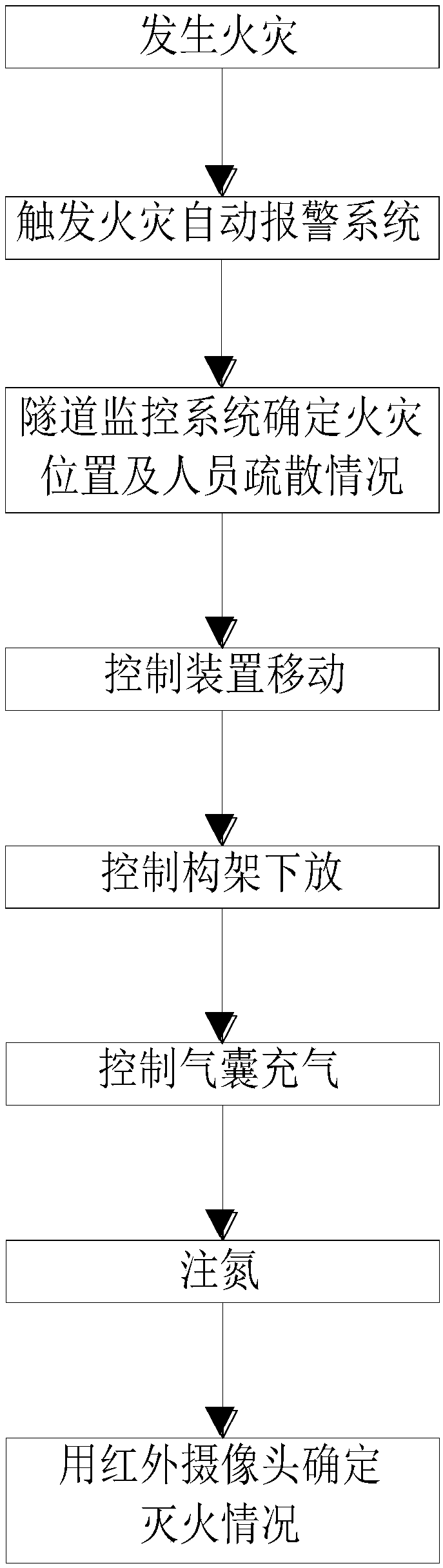
[0030] In order to make the object, technical solution and advantages of the present invention clearer, the present invention will be further described in detail below in conjunction with the accompanying drawings and embodiments. It should be understood that the specific embodiments described here are only used to explain the present invention, not to limit the present invention.

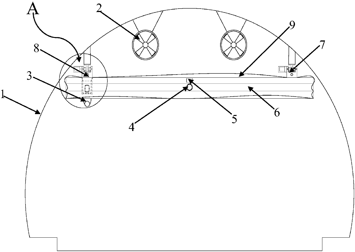
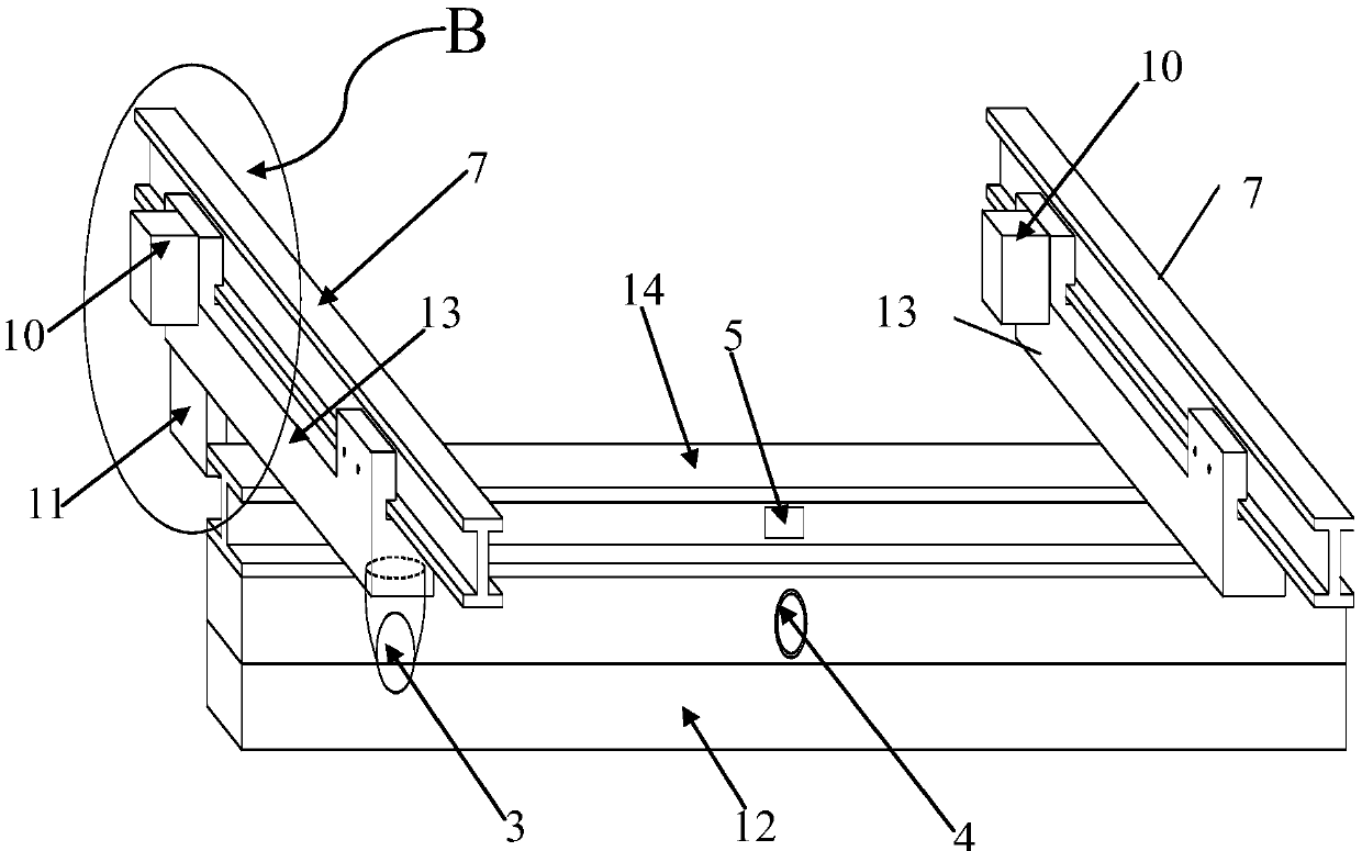
[0031] see Figure 2 to Figure 7 , a suffocation-type movable tunnel fire extinguishing device, including a high temperature resistant air bag 9, an air pressure sensor 5, a telescopic support frame 6 and a movable bridge frame 8, the tunnel inner wall 1 is a typical expressway tunnel two-lane section form, the upper part of the tunnel inner wall 1 A top beam 12 is provided, and two end beams 13 are arranged on the top beam 12, and the two end beams 13 are arranged in parallel, one of which is located at one end of the top beam 12, and the other is located at the other end of the top beam 12, and t...


PUM


Abstract

A suffocation type movable tunnel fire extinguishing device comprises a high-temperature-resisting air bag and a movable bridge. A top beam is arranged at the upper portion of the inner wall of a tunnel. Two end beams are arranged on the top beam and are parallel. The end beams are perpendicular to the top beam. A main beam is arranged between the two end beams. The movable bridge comprises guiderails, the end beams are arranged on the guide rails and can move along the guide rails, and the high-temperature-resisting air bag is arranged on the beam. According to the suffocation type movable tunnel fire extinguishing device, the highway tunnel operation safety performance is improved, and security threats to personnel left in the tunnel and damage to tunnel electromechanical and civil engineering facilities from the fire disaster are reduced. An inflation type air bag device is adopted for sealing the tunnel sections at the two ends of a fire source, high-temperature gas and a large amount of smoke generated by the fire disaster are isolated, and fire disaster spreading and toxic gas diffusion can be effectively controlled.

Description

technical field [0001] The invention relates to the field of tunnel fire-fighting facilities, in particular to a suffocating type movable tunnel fire-extinguishing device. Background technique [0002] With the continuous improvement of my country's economic development level, a large number of mountainous roads, railways and other transportation infrastructure have been vigorously developed, which has led to an increase in the number of tunnel construction, but also brought serious traffic fire accidents. The statistical analysis of accidents in tunnels shows that whether it is ordinary roads or expressways, accidents directly or indirectly related to fire account for a very large proportion, and serious and extraordinarily serious accidents account for a very high proportion. Therefore, how to embody the guiding ideology of "people-oriented, safety first" and take effective measures to reduce or even avoid similar traffic fire accidents during the road operation period is ...

Claims


Application Information

Patent Timeline
Patent Type & Authority Applications(China)
IPC IPC(8): A62C3/02A62C2/06A62C2/24A62C37/00A62C99/00
CPCA62C2/06A62C2/24A62C3/0221A62C37/00A62C99/0018
Inventor 杨凯齐群李博巩悦张馨予王利宝陈辉
Owner CHANGAN UNIV
Why Eureka
Try Eureka