
Oil paint mixing device

A technology of mixing device and paint, applied in the direction of spraying device, etc., can solve the problems of difficult liquid mixing, difficult mixing evenly, uneven mixing, spraying effect and liquid construction effect, etc., so as to improve the mixing effect and intensify the effect of paint mixing.

Active Publication Date: 2018-07-06
河北晨虹油漆有限公司
View PDF8 Cites 1 Cited by
  • Summary
  • Abstract
  • Description
  • Claims
  • Application Information

AI Technical Summary

Problems solved by technology

However, it is obvious that this method has great disadvantages: the color mixing process is cumbersome; the color of the second mixing paint is likely to have errors from the first mixing color
[0005] However, a problem that must be faced when using the above-mentioned equipment is how to mix the prepared paint evenly
Because, if it is not mixed evenly, it is difficult to get the standard color of the paint; but because the paint is a thick liquid with a certain viscosity, it is difficult to mix it evenly
[0006] In the spraying site and liquid construction occasions, the process that is often used is to mix the paint or liquid. The existing mixing and stirring measures are to use a hand-held stick to stir or use a motor to drive the stirring blade to stir the liquid to make it fully mixed evenly. The stirring process of this kind of treatment will waste a lot of time, and the stirring blade keeps rotating in one direction at a fixed position during the stirring process, it is difficult to make the liquid fully mixed, especially when the amount is relatively large, it is difficult to mix evenly, and the mixing is uneven It will have a great impact on the effect of spraying and liquid construction, so an improved process equipment is needed to fully mix the paint and liquid evenly

Method used


Image

  • Oil paint mixing device
  • Oil paint mixing device
  • Oil paint mixing device

Examples


Embodiment Construction

[0025] Further detailed explanation through specific implementation mode below:

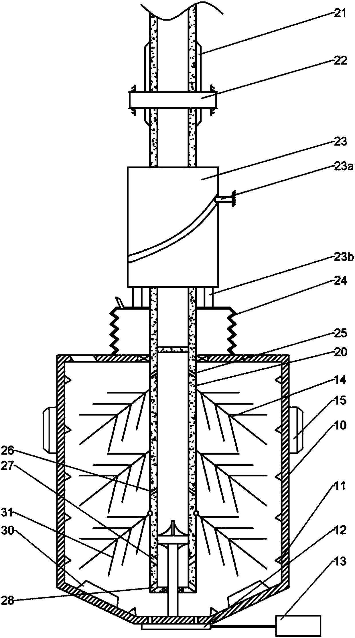
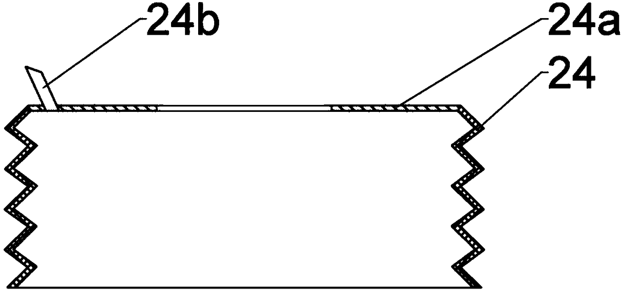
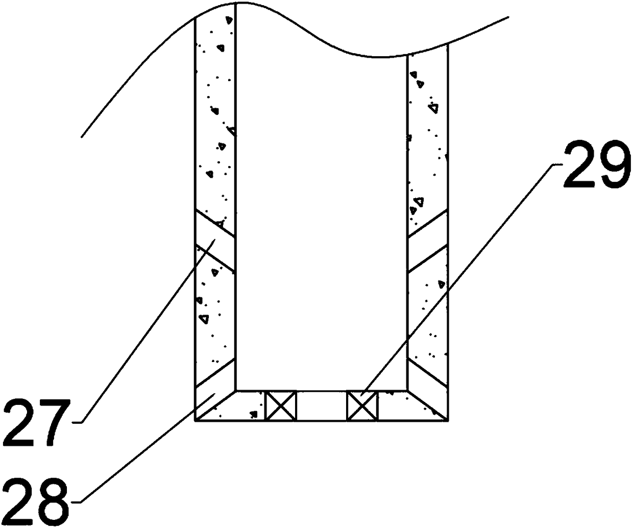
[0026] The reference signs in the accompanying drawings of the description include: mixing tank 10, air outlet nozzle 11, baffle plate 12, hydraulic cylinder 13, first stirring rod 14, outer ring gear 15, main shaft 20, spline section 21, drive gear 22, cylinder Cam 23, guide pin 23a, top block 23b, blower cover 24, upper liquid outlet 25, upper liquid inlet 26, lower liquid outlet 27, lower liquid inlet 28, sealing ring 29, stirring teeth 30, second stirring rod 31.

[0027] The technical solutions of the present invention will be clearly and completely described below in conjunction with the accompanying drawings. Apparently, the described embodiments are some of the embodiments of the present invention, but not all of them. Based on the embodiments of the present invention, all other embodiments obtained by persons of ordinary skill in the art without making creative efforts belong to the pro...


PUM


Abstract

The invention discloses an oil paint mixing device which comprises a machine frame and further comprises a main shaft, an air blowing cover, a mixing tank and a piston located in the mixing tank. Themain shaft, the air blowing cover, the mixing tank and the piston are arranged from top to bottom along the machine frame. A driving gear is rotationally arranged on the machine frame, the main shaftis hollow, the upper portion of the main shaft is in spline connection with the driving gear, the middle of the main shaft is provided with a cylindrical cam, a guide pin column is correspondingly arranged on the machine frame, the lower portion of the main shaft stretches into the mixing tank and is internally provided with a cavity, the outer wall of the cavity is sequentially provided with an upper liquid outlet, an upper liquid inlet, a lower liquid outlet and a lower liquid inlet from top to bottom, and the outer wall of the cavity is further provided with a plurality of first stirring rods fixed to the outer wall of the cavity and a plurality of second stirring rods hinged to the outer wall of the cavity from top to bottom.

Description

technical field [0001] The invention relates to a mixing device, in particular to a paint mixing device. Background technique [0002] Paint English name: paint or coating. Paint is a chemical mixture coating that can firmly cover the surface of objects for protection, decoration, marking and other special purposes. [0003] People use paint when decorating houses, making furniture or other products. According to different needs or personal preferences, users will choose paints of different colors. Due to the limited variety of paint colors sold by general manufacturers, it is difficult to meet people's needs, so people mix paints of different colors in a certain proportion according to their own needs, thereby forming a new color paint. Here we call the paint used for blending as the basic color paint. Traditional paint mixing is done manually. Operators usually get the color they want based on their own experience or different experiments. But, obviously, there is very...

Claims


Application Information

Patent Timeline
Patent Type & Authority Applications(China)
IPC IPC(8): B05B15/25
Inventor 廖成涛
Owner 河北晨虹油漆有限公司
Learn More