Vacuum negative-pressure grouting method and system

A technology of vacuum negative pressure and grouting machine, which is applied in construction, building structure, processing of building materials, etc., can solve problems such as difficult inspection, slurry cavity, lack, etc., achieve outstanding technical advantages, solve industry problems, guarantee The effect of reliability

Active Publication Date: 2018-07-06
CABR CONSTR MACHINERY TECH +1
View PDF6 Cites 7 Cited by
  • Summary
  • Abstract
  • Description
  • Claims
  • Application Information

AI Technical Summary

Problems solved by technology

[0003] But at present, in the construction of sleeve grouting connection of prefabricated component joints, the industry lacks special sleeve grouting equipment that can effectively control the fullness of grouting. The existing equipment used in construction is not ideal. Workers mainly rely on experience to operate, and there are many deficiencies.
The fullness control of sleeve grouting is a difficult point in the prefabricated steel bar connection technology. Since this process is hidden and difficult to detect, the existing construction mainly uses overflow holes for observation. There is a flow dead zone between the flow connection port and the tail of the sleeve, which is easy to accumulate gas and the water from the slurry. Due to the lack of effective methods to ensure that the above-mentioned gas and the water from the slurry in the sleeve are completely drained, and the grouting material Due to various other factors such as performance, deflection of sleeve and steel bar installation, there may be a slurry cavity in the sleeve after grouting, and it is difficult to check, which makes the grouting fullness of the sleeve difficult to control, which leads to the failure of prefabricated components. It is difficult to guarantee the connection strength between them, which may leave quality problems for prefabricated construction projects.

Method used


Image

  • Vacuum negative-pressure grouting method and system
  • Vacuum negative-pressure grouting method and system
  • Vacuum negative-pressure grouting method and system

Examples


Embodiment Construction

[0034] Below in conjunction with accompanying drawing, describe the best implementation mode of the present invention through preferred embodiment, the specific implementation mode here is to illustrate the present invention in detail, and should not be interpreted as the limitation of the present invention, without departing from the spirit and essence of the present invention Various changes and modifications can be made within the scope of the present invention, and these should be included in the protection scope of the present invention.

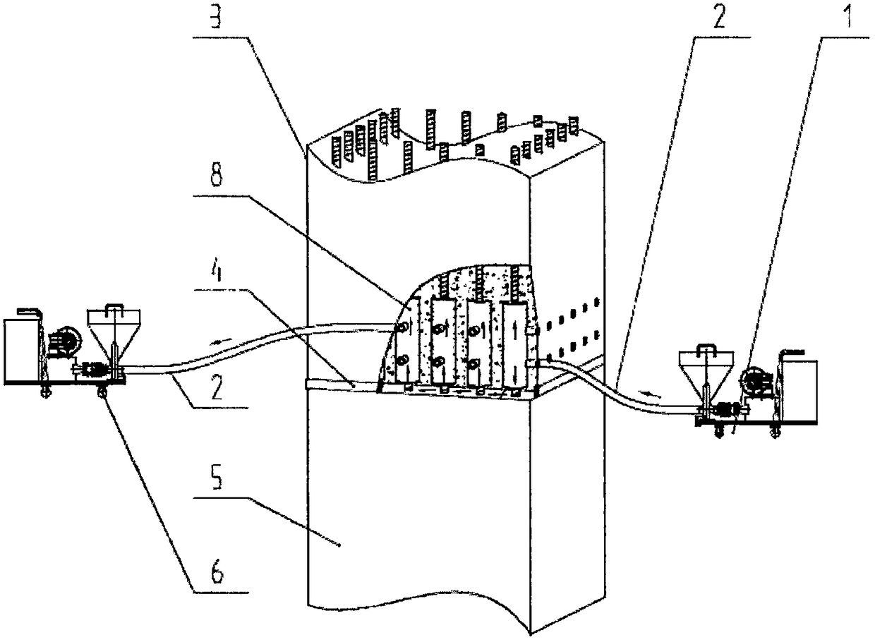
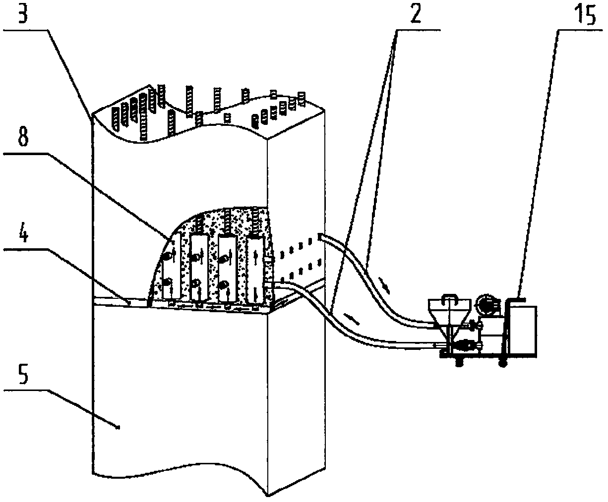
[0035] see Figure 1-4 , The invention provides a vacuum negative pressure grouting method. The vacuum negative pressure grouting method achieves full grouting through the action of vacuum negative pressure and pressure-holding grouting, and uses a combination of two machines to perform grouting operations, including the following steps:

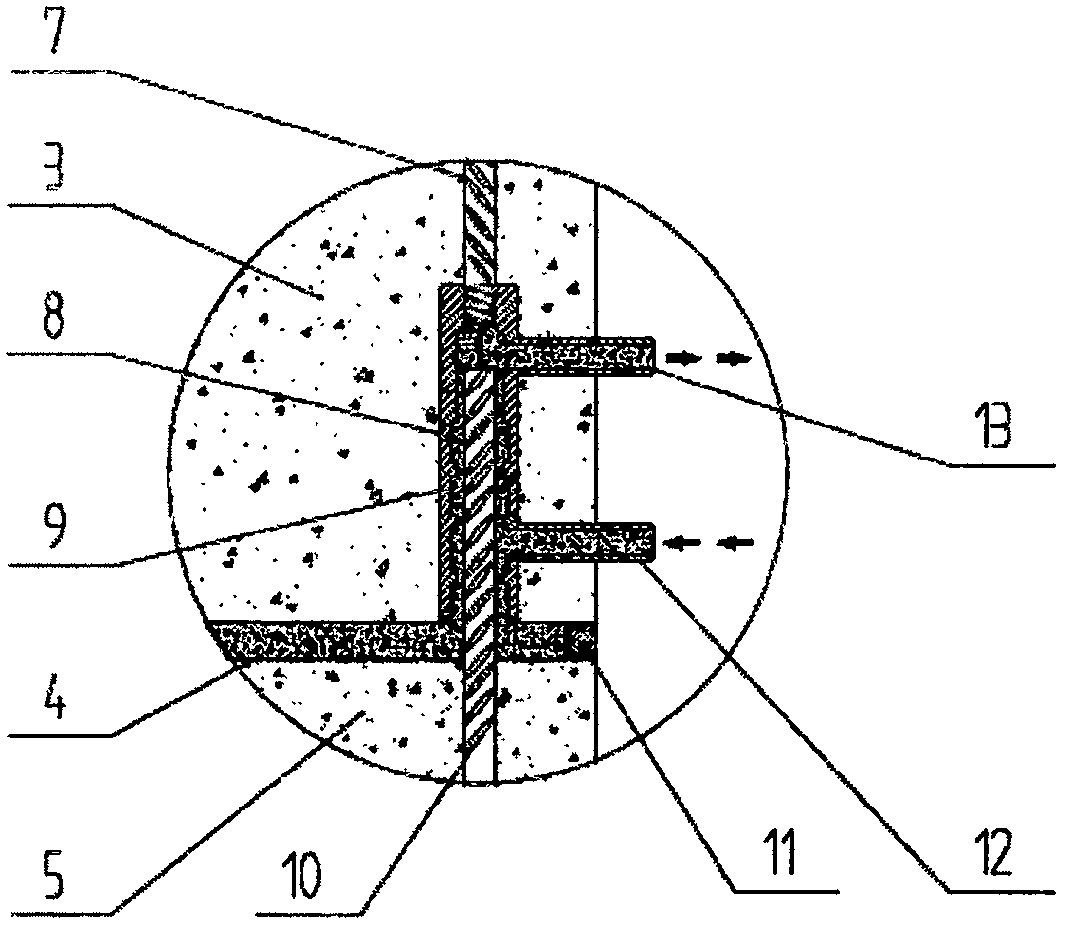
[0036] The first grouting machine 1 transports the grout 9 from the grout inlet 12 of the sleeve ...


PUM


Abstract

The invention discloses a vacuum negative-pressure grouting method. Through the effect of vacuum negative-pressure and pressure maintaining grouting, full grouting is achieved, and two machines are combined to carry out the grouting operation. The vacuum negative-pressure grouting method comprises the following steps that through a first grouting machine, a grouting material is conveyed from a grout inlet of a sleeve to a communicating cavity of a connected element and the inner portion of the sleeve by a pipeline; when the grouting material is about to flow out from a post-filling overflow opening of the sleeve, vacuum negative-pressure is formed inside the sleeve by the suction of a second grouting machine at the overflow opening, so that residual air in the sleeve can be sucked out, slurry can leak out secrete free water, and the whole sleeve and the gap area of the communicating cavity are filled with the grouting material; and the first grouting machine continues to perform pressure maintaining grouting at the grout inlet, so that it is guaranteed that the sleeve and the filling parts of the element is full of the grouting material.

Description

technical field [0001] The invention relates to a grouting method and system, and is especially suitable for node connection construction of prefabricated assembly buildings, prefabricated concrete wind power towers and other prefabricated components connected by the grouting method. Background technique [0002] In the prefabricated building structure, most of the joints of prefabricated components in my country are connected by sleeve grouting. The sleeve after grouting bears the role of force transmission between components, and its connection quality directly affects the safety of the prefabricated concrete structure. [0003] But at present, in the sleeve grouting connection construction of prefabricated component nodes, there is a lack of special sleeve grouting equipment that can effectively control the grouting fullness in the industry. The existing construction equipment is not ideal, and workers mainly rely on experience to operate, which has many shortcomings. The...

Claims


Application Information

Patent Timeline
IPC IPC(8): E04G21/02
CPCE04G21/02
Inventor 张声军陈炜宁曹国巍石小虎周磊韦赵滨
Owner CABR CONSTR MACHINERY TECH
Why Eureka
Try Eureka