Corner three-way connector and mounting method thereof

A technology of corner tees and connectors, which is applied in the direction of connecting components, rods, mechanical equipment, etc., can solve the problems of poor stability of the connection structure and easy sloshing, etc., so as to improve the connection rigidity, increase the contact rigidity, and make it difficult to connect The effect of exercise

Inactive Publication Date: 2018-07-06
SHANGYU MEISI CRAFTS
View PDF6 Cites 2 Cited by
  • Summary
  • Abstract
  • Description
  • Claims
  • Application Information

AI Technical Summary

Problems solved by technology

[0004] As for the above-mentioned three-way connector, no matter it is a type A three-way connector or a type B three-way connector, multiple steel pipes can be connected by directly inserting the connecting part on the three-way connector into the steel pipe during use. The frame structure of various cabinets and shelves can be built through the function of multiple three-way connectors. However, in the process of using this kind of three-way connector, it was found that in order to ensure that the connecting part can be inserted into the steel pipe, the three-way connector The size of the connecting part must be smaller than the size of the inner cavity of the steel pipe, so there will be a gap between the connecting part of the tee joint and the inner wall of the steel pipe, so that the frame structure built with this tee joint is detachable. , but it is very easy to shake during use, which leads to poor stability of the connection structure between the tee joint and the steel pipe

Method used


Image

  • Corner three-way connector and mounting method thereof
  • Corner three-way connector and mounting method thereof
  • Corner three-way connector and mounting method thereof

Examples


Embodiment Construction

[0039] The present invention will be described in further detail below in conjunction with the accompanying drawings.

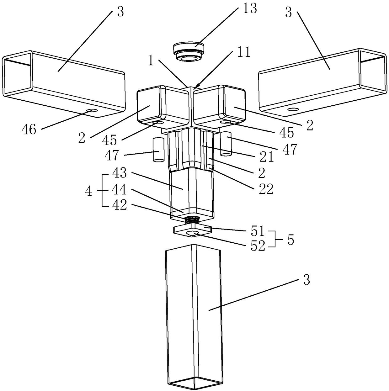
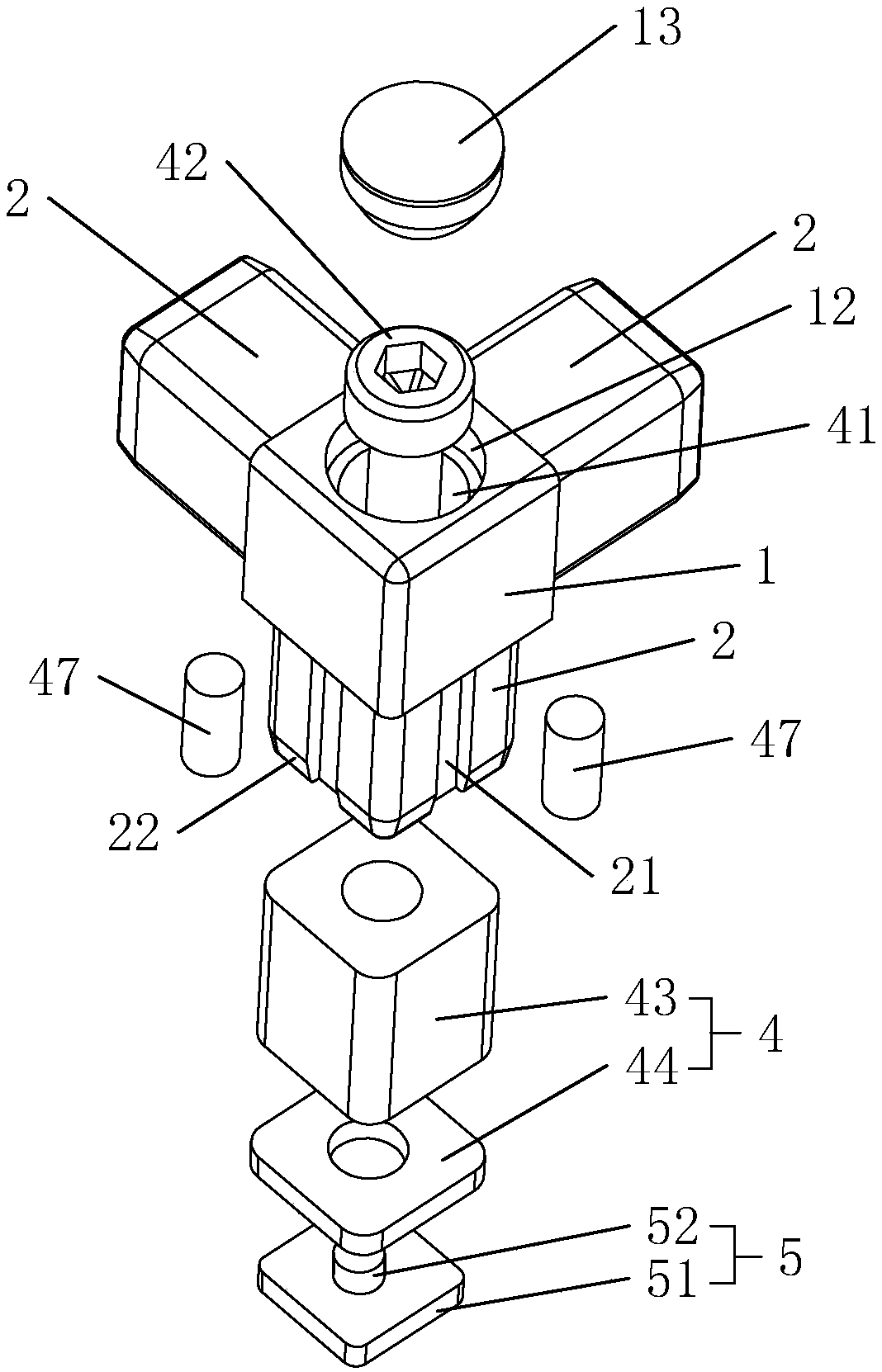
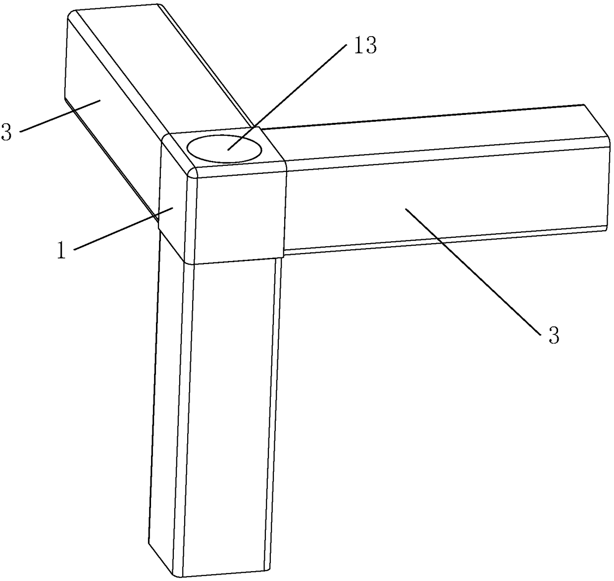
[0040] Such as figure 1 As shown, a corner tee connector is formed by integral die-casting of hard aluminum alloy, which includes a connecting main body 1 and three connecting legs 2. On each side wall, and between the connecting leg 2 and the connecting main body 1, there is a stop step 11 for the steel pipe 3 to resist; on each side wall of one of the connecting legs 2, there is a lengthwise direction parallel to the connecting leg 2. The deformation groove 21 in the length direction, after the deformation groove 21 is opened, a chamfer 22 surrounding the connection foot 2 is provided on the end of the connection foot 2 away from the connection body 1 .

[0041] Such as figure 1 with figure 2 As shown, it also includes a fixed structure 4 for fixedly connecting the connecting leg 2 with the steel pipe 3. The fixed structure 4 includes a mounting hole 41...


PUM


Abstract

The invention discloses a corner three-way connector and a mounting method thereof, relates to hardware accessories, and aims at solving the problem of low structure stability of a connecting structure of an existing three-way connector. The corner three-way connector comprises a connector body, and connecting supporting legs which are fixedly connected to the connector body, wherein a fixing structure is arranged on each connecting supporting leg and comprises a mounting hole which is formed in the connector body and passes through the connector body and any one of the connecting supporting leg, an adjusting part which is mounted in the mounting hole, an elastic expansion body which sleeves the adjusting part, and an extruding part which is in thread connection with the adjusting part; the sections of the elastic expansion bodies, the extruding parts, the connecting supporting legs and inner cavities of steel pipes are of polygon shapes which fit each other; after being expanded, theelastic expansion bodies can be extruded relative to the inner walls of the steel pipes, and thus the elastic expansion bodies can move relative to the corresponding steel pipes; the elastic expansionbodies are fixed relative to the corner three-way connector, so that the corner three-way connector is hard to move relative to the steel pipes, and as a result, the stability of the connecting structure is improved.

Description

technical field [0001] The invention relates to hardware fittings, in particular to a corner tee connector and an installation method thereof. Background technique [0002] Household items such as chairs, flower pot stands, and cabinets are usually based on a frame structure composed of overlapping steel pipes. According to the old technology, when multiple steel pipes are connected to each other, they are usually fixed by welding. The welded frame structure cannot be disassembled and is bulky. It is inconvenient to transport for mass shipments. Therefore, detachable connections are mostly used to build frames, and detachable connections need to be carried out with the help of connectors. [0003] At present, the authorized announcement number is CN206471083U, and the Chinese utility model with the authorized announcement number 2017.09.05 discloses a detachable light box bracket, which includes a plurality of three-way connectors and sleeve rods for socketing with the three...

Claims


Application Information

Patent Timeline
Patent Type & Authority Applications(China)
IPC IPC(8): F16B7/08
CPCF16B7/00
Inventor 顾红辉
Owner SHANGYU MEISI CRAFTS
Why Eureka
Try Eureka