Optical fiber fluorescent all-optical magnetic field sensor and system

A magnetic field sensor and optical fiber technology, which is applied in the use of magneto-optical equipment to measure the magnetic field, the size/direction of the magnetic field, etc., which can solve safety hazards such as magnetic particle diffusion pollution, optical refractive index changes around the fiber core, and complex core device structures, etc. problems, to achieve the effect of easy long-term use, easy processing, and simple core structure

Pending Publication Date: 2018-07-06
UNIV OF SCI & TECH OF CHINA
View PDF0 Cites 14 Cited by
  • Summary
  • Abstract
  • Description
  • Claims
  • Application Information

AI Technical Summary

Problems solved by technology

[0003] However, the existing optical fiber magnetic field sensing technology in optical fiber sensing technology often needs to add magnetostrictive materials and magnetic nanoparticle materials into or around the optical fiber, and use the conversion of magnetic field to deformation to read the deformation information with light, or magnetic field Drive particle redistribution resulting in changes in the refractive index of light around or within the fiber core
However, the above-mentioned added materials often bring potential safety hazards or pollutants (heat generation by induction current, diffusion pollution by magnetic particles) in special application environments (such as high-voltage substations and other environments with high-intensity induction electromagnetic fields), and most of the core The structure of the device is complex, and it is also susceptible to environmental interference such as temperature

Method used


Image

  • Optical fiber fluorescent all-optical magnetic field sensor and system
  • Optical fiber fluorescent all-optical magnetic field sensor and system
  • Optical fiber fluorescent all-optical magnetic field sensor and system

Examples


Embodiment Construction

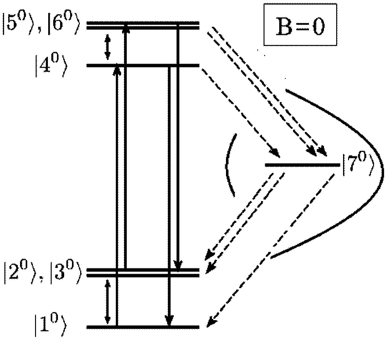
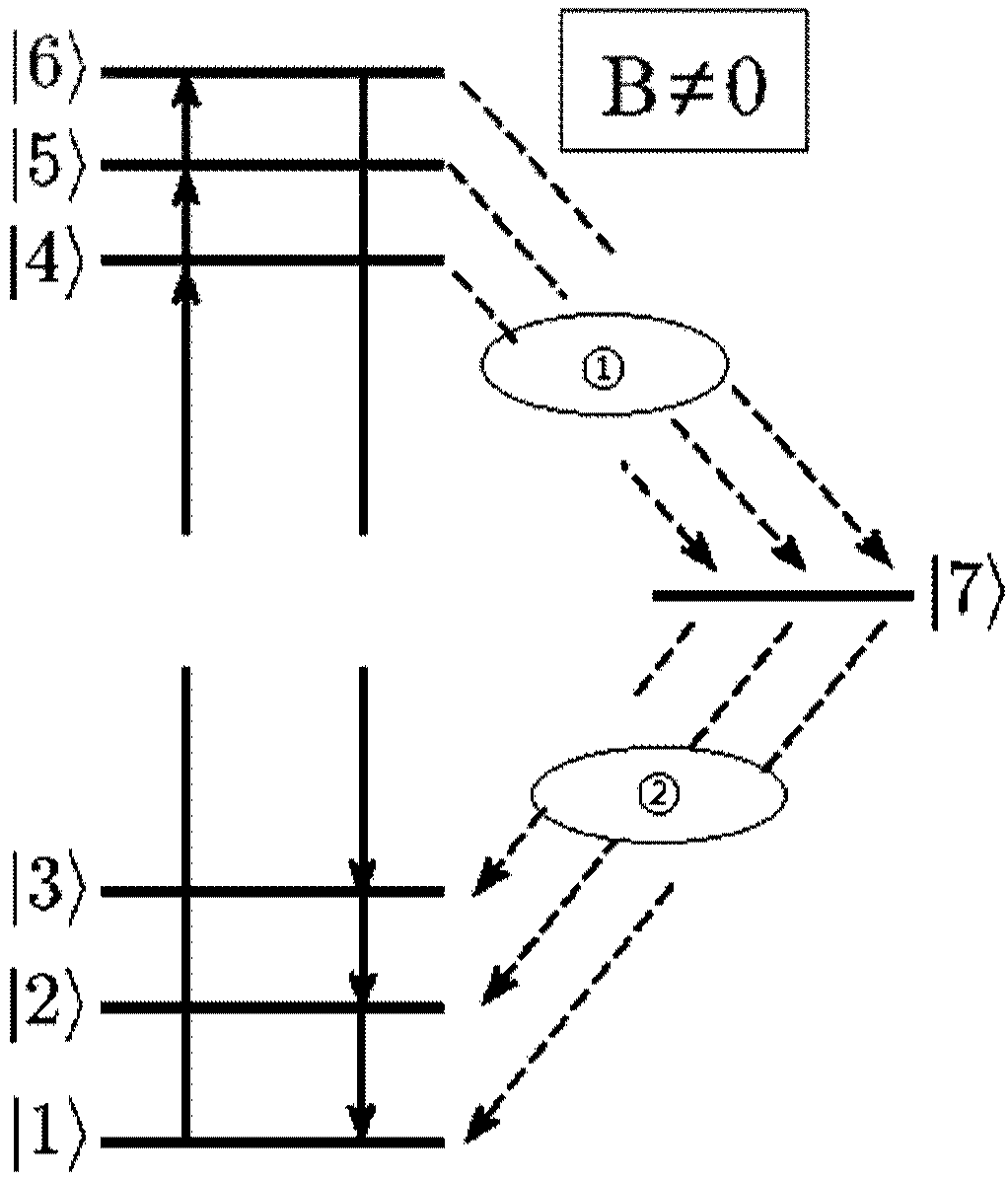
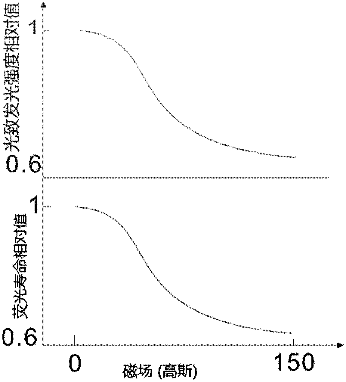
[0025] In order to make the object, technical solution and advantages of the present invention clearer, the present invention will be further described in detail below in conjunction with specific embodiments and with reference to the accompanying drawings. The advantages and effects of the present invention will be more obvious through the content disclosed in the present invention. The drawings accompanying the description herein are simplified and used for illustration purposes. The number, shape and size of the components shown in the drawings can be modified according to the actual situation, and the configuration of the components may be more complicated. Other aspects of practice or application can also be carried out in the present invention, and various changes and adjustments can be made without departing from the defined spirit and scope of the present invention.

[0026] According to the existing optical fiber magnetic field sensing technology, it is often necessa...


PUM


Abstract

The invention discloses an optical fiber fluorescent all-optical magnetic field sensor and a sensing system. The sensor comprises an optical fiber and a nano-diamond NV color-centered fluorescent layer which is arranged at one end of the optical fiber. The nano-diamond NV color-centered fluorescent layer is attached to one end of the optical fiber through the optical glue. The optical fiber comprises an inner optical fiber core and the nano-diamond NV color center is arranged at one end of the optical fiber through being embedded at one end of the optical fiber core. According to the invention, only optical signals in the optical fiber are measured based on the sensor technology. Therefore, the measurement response frequency is high, and the core structure is simple.

Description

technical field [0001] The invention belongs to the field of optical fiber fluorescence sensors, and further relates to an optical fiber fluorescence all-optical magnetic field sensor and an optical fiber fluorescence all-optical magnetic field sensing system. Background technique [0002] Optical fiber sensors are widely used in the measurement of physical quantities such as displacement, vibration, rotation, pressure, bending, strain, speed, acceleration, current, magnetic field, voltage, humidity, temperature, sound field, flow, concentration, PH value and strain. Among the main reasons for the widespread application in the current information age, there are three important ones. One is because the optical fiber has many excellent material properties, such as: anti-electromagnetic and atomic radiation interference performance, thin diameter, soft, light mechanical properties; electrical properties of insulation, no induction; water resistance, high temperature resistance,...

Claims


Application Information

Patent Timeline
Patent Type & Authority Applications(China)
IPC IPC(8): G01R33/032
CPCG01R33/032
Inventor 李燊陈向东赵博文孙方稳郭光灿
Owner UNIV OF SCI & TECH OF CHINA
Why Eureka
Try Eureka