
A Pattern Reconfigurable Filter Antenna

A technology for reconstructing filtering and filtering antennas, applied in the direction of antennas, resonant antennas, antenna grounding switch structures, etc., can solve the problems of antenna frequency characteristics and impedance characteristics, etc. The effect of broadband performance

Active Publication Date: 2020-07-31
NANJING UNIV OF AERONAUTICS & ASTRONAUTICS
View PDF4 Cites 1 Cited by
  • Summary
  • Abstract
  • Description
  • Claims
  • Application Information

AI Technical Summary

Problems solved by technology

In this way, it will have a great impact on the frequency characteristics and impedance characteristics of the antenna, and the filter antenna requires better impedance characteristics and frequency characteristics, so the combination of the pattern reconfigurable antenna and the filter antenna has become a big problem

Method used


Image

  • A Pattern Reconfigurable Filter Antenna
  • A Pattern Reconfigurable Filter Antenna
  • A Pattern Reconfigurable Filter Antenna

Examples


Embodiment Construction

[0024] The pattern reconfigurable microstrip filter antenna of the present invention will be described in detail below in conjunction with the accompanying drawings.

[0025] In the description of the present invention, it should be understood that the orientations or positional relationships indicated by the terms "left side", "right side", "upper", "lower" are based on the orientations or positional relationships shown in the accompanying drawings, and are only For the purpose of describing the present invention and simplifying the description, rather than indicating or implying that the device or element referred to must have a specific orientation, be constructed and operate in a specific orientation, "first", "second" and the like do not represent components importance, and therefore should not be construed as limiting the invention. The specific dimensions used in this embodiment are only for illustrating the technical solution, and do not limit the protection scope of t...


PUM

PropertyMeasurementUnit
thicknessaaaaaaaaaa
relative permittivityaaaaaaaaaa

Abstract

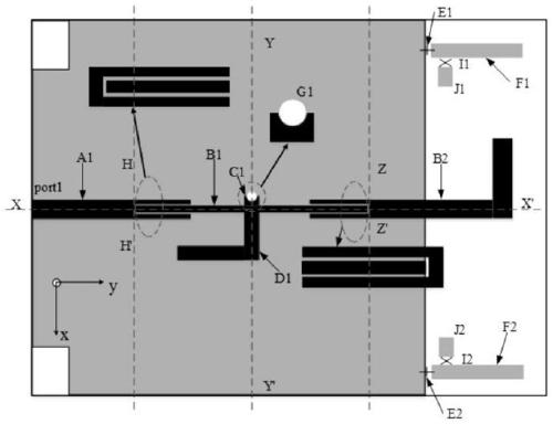
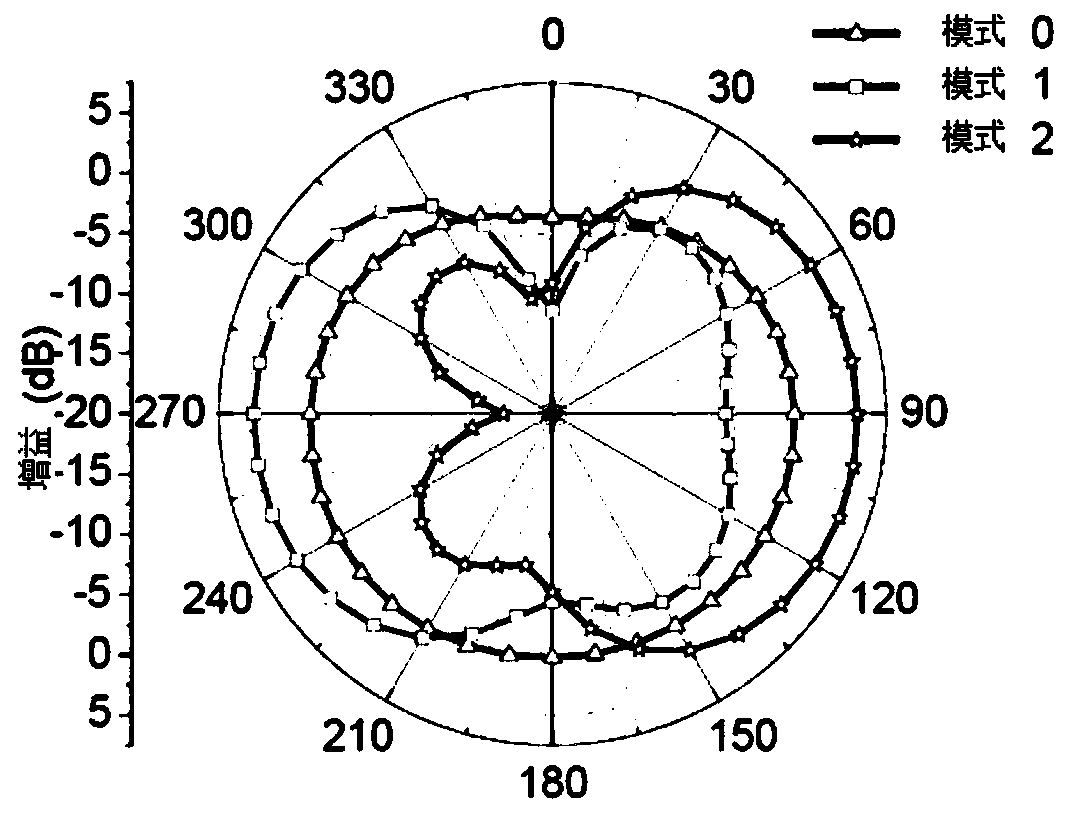
The invention discloses a pattern-reconfigurable filter antenna, comprising a dielectric substrate and a filter antenna module and a control module located above and below the dielectric substrate respectively. The filter antenna module comprises a feeder line, a multimode resonator and a transmitting antenna. Energy is transmitted in a coupling way between the multimode resonator on one hand andthe feeder line and the transmitting antenna on the other hand. The control module comprises a reflector and a reflector switch. The reflector is used for reflecting the electromagnetic wave radiatedby the transmitting antenna to control the radiation direction of the transmitting antenna. The reflector switch is used for controlling the enabling of the reflector. The impedance characteristic andfrequency characteristic of the filter antenna can be kept basically unchanged while the pattern of the filter antenna is reconfigurable.

Description

technical field [0001] The invention relates to a microstrip filter antenna, in particular to a reconfigurable microstrip filter antenna with a pattern. [0002] technical background [0003] With the rapid development of wireless communication technology, the reconfigurable antenna has the potential to avoid noisy environments, and at the same time, it can avoid electronic interference, improve the security of communication systems, and can better and more accurately convey signals to target users. In order to save energy, the pattern reconfigurable antenna is of great significance in modern communication systems. The filter at the front end of the antenna can filter out clutter and improve the selectivity of the passband edge, but the filter and antenna occupy a large volume in the system and cannot meet the requirements of modern communication systems. The filter antenna can achieve filtering and radiation Functional components, and the integrated design of the filter and...

Claims


Application Information

Patent Timeline
Patent Type & Authority Patents(China)
IPC IPC(8): H01Q1/38H01Q1/50H01Q3/44H01Q9/42H01Q15/14H01Q19/02H01P7/08
CPCH01P7/082H01Q1/38H01Q1/50H01Q3/44H01Q9/42H01Q15/14H01Q19/021
Inventor 邓宏伟徐涛薛一凡刘飞丁吉
Owner NANJING UNIV OF AERONAUTICS & ASTRONAUTICS
Learn More