Train brake system, multiple unit train set and brake control method

A brake control and brake system technology, applied in brake safety systems, brake components, brakes, etc., can solve the problem of increased wear and tear, affecting the normal operation of trains, communication network bandwidth, transmission rate and cost that cannot meet the requirements of the brake system The needs of technological development and other issues to achieve the effect of improving reliability, ensuring normal operation, and eliminating faults and false alarms

Inactive Publication Date: 2018-07-10
CRRC QINGDAO SIFANG ROLLING STOCK RES INST
View PDF8 Cites 15 Cited by
  • Summary
  • Abstract
  • Description
  • Claims
  • Application Information

AI Technical Summary

Problems solved by technology

With the intelligent development of the braking system, more and more information needs to be transmitted, and the amount of data is increasing. The bandwidth, transmission rate and cost of the traditional communication network can no longer meet the needs of the development of the braking system technology. The Ethernet-based network architecture has been introduced successively as the train communication network for the next generation of EMUs and urban rail vehicles
However, when the network system of a certain vehicle fails, such as the network card failure of the braking system of a certain vehicle, the network control of the single vehicle braking will fail.
In this case, it is necessary to stop and isolate the braking of the faulty vehicle before resuming operation: when the lost braking force is small, the remaining available braking force of other vehicles can be used to supplement the braking force lost by the faulty vehicle , there is no speed limit, but it will increase the wear of other cars; when the loss of braking force is large, speed limit is required, which affects the normal operation of the train

Method used


Image

  • Train brake system, multiple unit train set and brake control method
  • Train brake system, multiple unit train set and brake control method

Examples


Embodiment 1

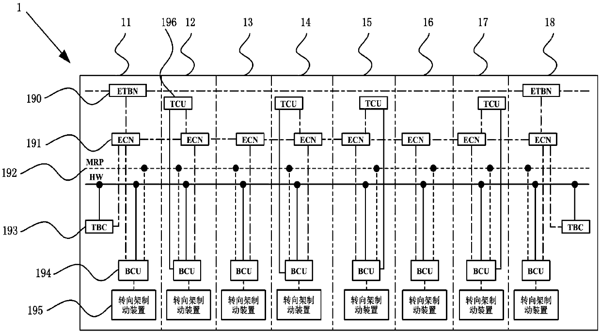
[0040] Such as figure 1 The shown train brake system 1 includes traction brake controllers 193 and train backbone network nodes 190 located at both ends of the driver's cab, a traction control unit 196 arranged in the motor car, and a brake control unit 196 arranged in each car. 194, a bogie braking device 195 and an Ethernet switch 191. Further, this embodiment is described taking Ethernet as an example. Ethernet adopts a two-level bus topology, which is divided into train level and vehicle level; wherein different network management units at the train level communicate with each other through the train backbone network node 190. To connect, each vehicle at the vehicle level has a network interface and is connected to each other through the Ethernet switch 191 of the vehicle.

[0041] Continue to see figure 1 , the traction brake controller 193, the brake control unit 194 and the traction control unit 196 all have a network interface and a hardwire interface, and the tracti...


PUM


Abstract

The invention discloses a train brake system. The train brake system comprises traction brake controllers, traction control units, brake control units and brake devices, wherein the traction control units are arranged in multiple unit trains and the brake control unit and the brake device are arranged in each multiple unit train; the brake control units are connected with the brake devices throughair passages; network interfaces and hard wire interfaces are formed in the traction brake controllers, the traction control units and the brake control units; the traction brake controllers and thebrake control units are simultaneously connected with hard wires through network buses; the traction control units and the brake control units are simultaneously connected with the hard wires throughthe network buses so that brake information can be simultaneously transmitted through communication networks and hard wires; and when the communication network has a fault, the transmission of the brake information of the multiple unit train with the network fault is controlled to be switched from using the communication network into using the hard wire, and the brake information of the rest normal multiple unit trains is still transmitted by the communication networks. The train brake system has the advantages that stopping or speed limiting is not needed, the reliability of the brake systemcan be improved and the normal operation of the train can be guaranteed.

Description

technical field [0001] The invention belongs to the field of vehicle braking control, and in particular relates to a train braking system, an EMU and a braking control method. Background technique [0002] At present, the braking systems of EMUs and urban rail vehicles mainly use one or a combination of TCN bus, ARCNET bus, RS485 bus, CAN bus, and Ethernet bus as the communication architecture. Therefore, the reliability of the network determines the availability of the braking system. In order to improve the availability of the braking system, the current system improves the reliability of the network by setting redundant network equipment. With the intelligent development of the braking system, more and more information needs to be transmitted, and the amount of data is increasing. The bandwidth, transmission rate and cost of the traditional communication network can no longer meet the needs of the development of the braking system technology. The Ethernet-based network a...

Claims


Application Information

Patent Timeline
Patent Type & Authority Applications(China)
IPC IPC(8): B61L23/00B61H11/06B60T17/22
CPCB60T17/228B61H11/06B61L23/00
Inventor 王令军赛华松赵杨坤胡淼路金昌张振超刘振
Owner CRRC QINGDAO SIFANG ROLLING STOCK RES INST
Why Eureka
Try Eureka