
Temperature self-compensating strain gauge

A strain gauge and self-compensation technology, applied in the field of sensing, can solve the problem of not being able to suppress the temperature effect of the strain gauge well, and achieve the effect of good temperature compensation and simple manufacturing process

Pending Publication Date: 2018-07-10
中国空气动力研究与发展中心超高速空气动力研究所
View PDF0 Cites 16 Cited by
  • Summary
  • Abstract
  • Description
  • Claims
  • Application Information

AI Technical Summary

Problems solved by technology

In this case, neither of the above two temperature compensation methods can well suppress the temperature effect of the strain gauge

Method used


Image

  • Temperature self-compensating strain gauge
  • Temperature self-compensating strain gauge
  • Temperature self-compensating strain gauge

Examples


Embodiment Construction

[0025] The novel temperature self-compensating strain gauge of the present invention will be described in further detail below in conjunction with the accompanying drawings and specific embodiments.

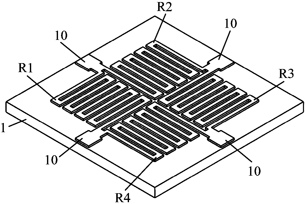
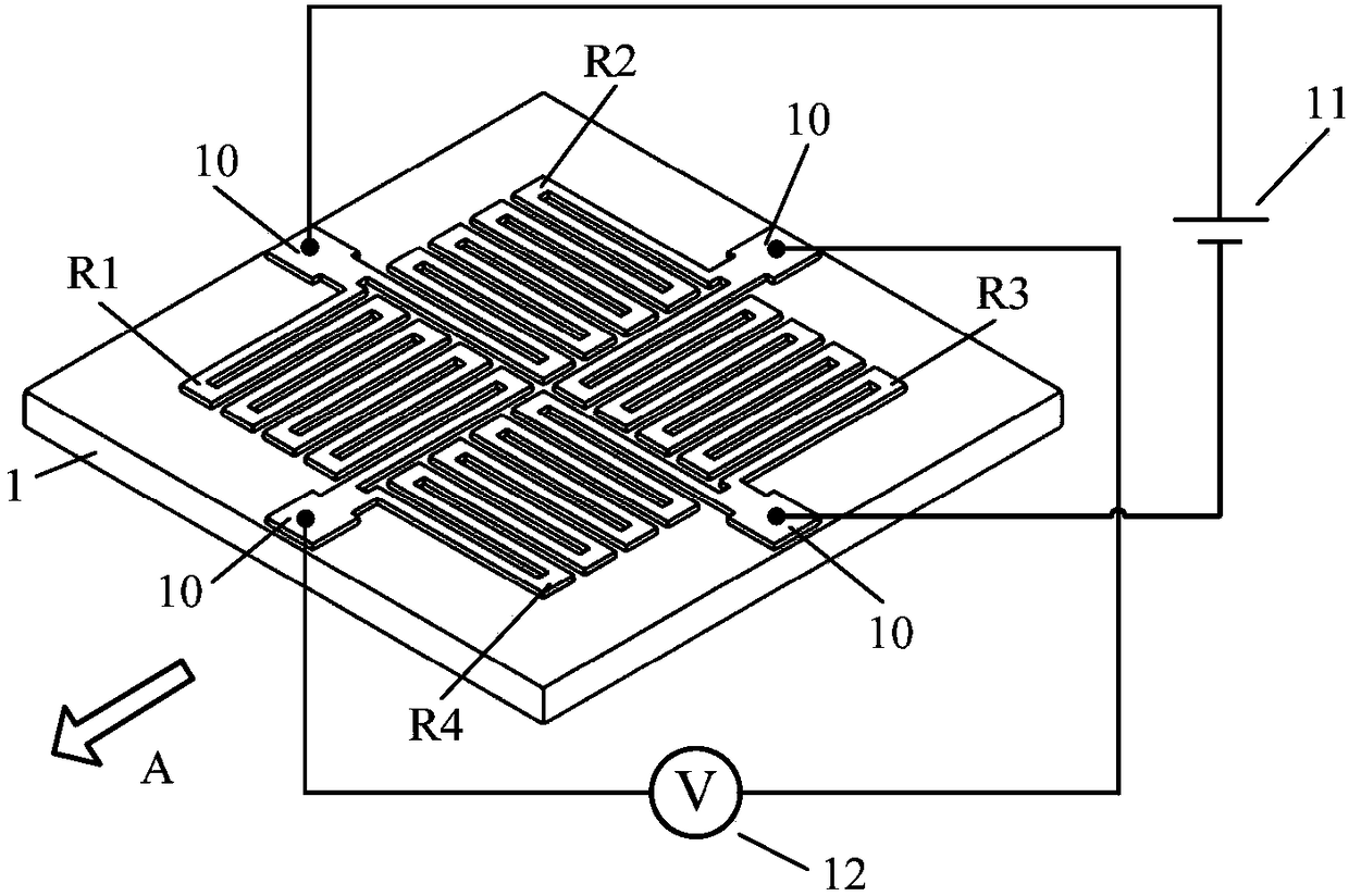
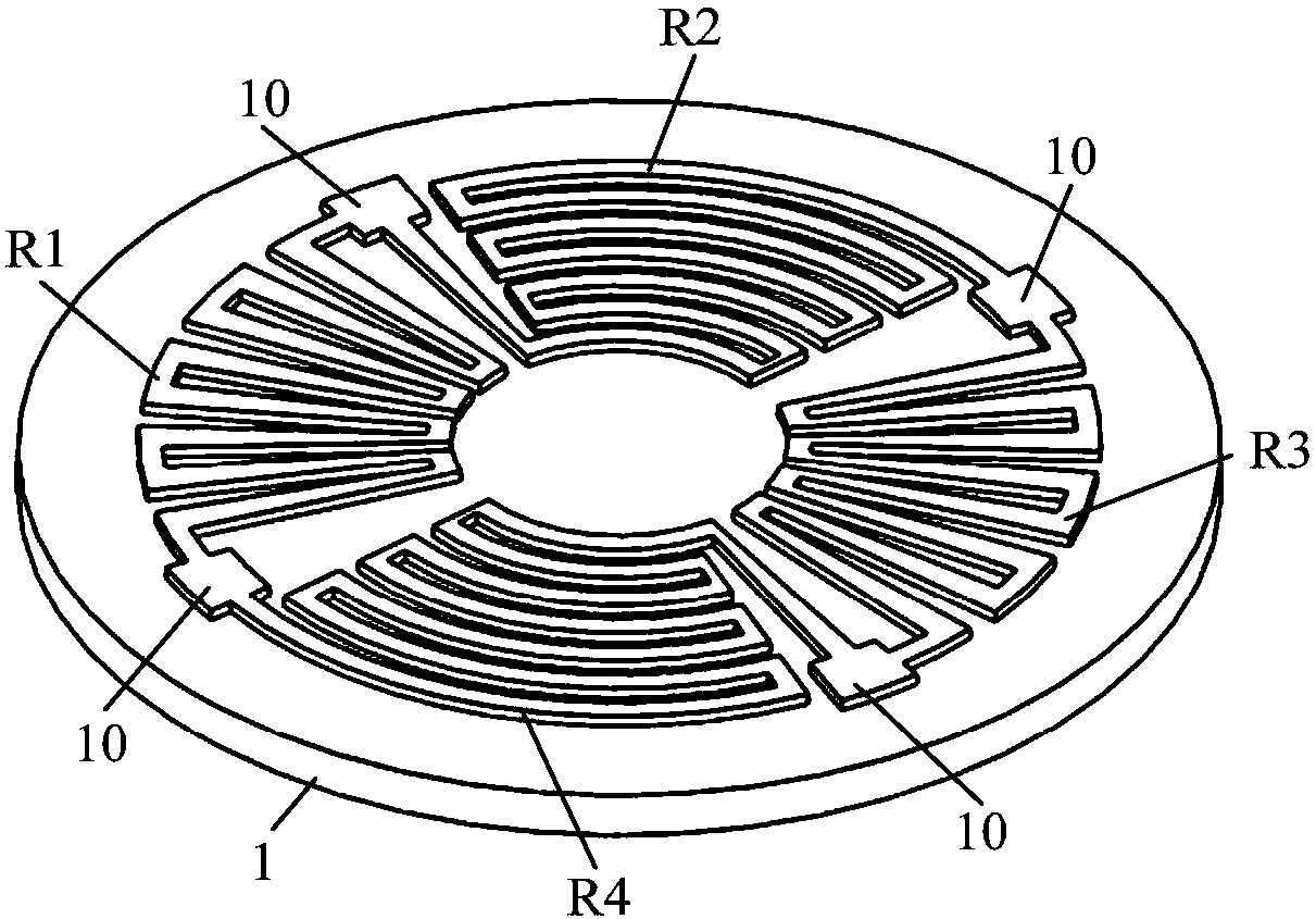
[0026] figure 1 It is a structural schematic diagram of a strain gauge of the present invention. The strain gauge is composed of a strain gauge base 1, lead electrodes 10 and four sensitive grids R1-R4 symmetrically distributed; the material for making the lead electrodes 10 can be the same as that of the sensitive grids R1-R4, or a material with better conductivity can be selected; the base The structures such as lead electrodes 10 and sensitive gates R1-R4 on 1 can be fabricated by pasting, sputtering, deposition, ion implantation, diffusion and other methods. Sensitive grids R1~R4 have the same size, and by using a uniform thickness and isotropic sensitive grid foil, the resistance value of sensitive grids R1~R4 can better meet:

[0027]

[0028] Therefore, the strain gau...


PUM


Abstract

The invention belongs to the field of sensing technologies, and specifically relates to a novel temperature self-compensating strain gauge used in a temperature-variable environment, particularly in an environment with temperature gradient. The strain gauge comprises a substrate, four electrodes and four sensitive grids, wherein the four electrodes and the four sensitive grids are arranged in a mutually orthogonal manner, and the four sensitive grids are formed by four isotropic sensitive grid foils which are the same in size and uniform in thickness; the four sensitive grids are mutually connected to form a Wheatstone bridge, two adjacent sensitive grids in the bridge form a current channel, and the four sensitive grids are mutually connected to form four current channels; and the four current channels are respectively connected with the four electrodes. The strain gauge can compensate measurement errors caused by a resistance temperature effect of the material of the sensitive gridsand thermal expansion of a sensitive element and a test piece through the self structure, so that the temperature compensation effect of the strain gauge can be well guaranteed only by depending on the consistency of the processing technology and material, and an additional temperature compensation circuit is not needed.

Description

technical field [0001] The invention belongs to the field of sensor technology, and in particular relates to a strain gauge for accurately measuring stress or strain in a variable temperature environment, especially with a temperature gradient. Background technique [0002] Strain gauges have been widely used in the measurement of structural stress and the production of sensors for various physical quantities (force, gravity, pressure, displacement, acceleration, and torque). Modern strain gauge technology is popular in aerospace, aviation, atomic energy, chemical industry, machinery, and construction. , transportation, and bioengineering. However, most strain gauges are very sensitive to temperature, and the disturbance output (temperature effect) and strain output caused by temperature are roughly within an order of magnitude. The most commonly used temperature compensation method is to use at least two identical strain gauges to form a Wheatstone bridge; another method i...

Claims


Application Information

Patent Timeline
IPC IPC(8): G01B7/16G01D3/036
CPCG01B7/18G01D3/036
Inventor 邱华诚
Owner 中国空气动力研究与发展中心超高速空气动力研究所
Learn More