Locking device of electric appliance

A technology for locking devices and electrical equipment, applied in the direction of coupling devices, components of connecting devices, circuits, etc., can solve the problems of affecting the use of electrical equipment, plugs of electrical equipment are knocked open, and no locking device is installed, so as to achieve convenient entry and exit, Avoid electric shock, convenient plug-in fastening effect

Active Publication Date: 2018-07-10
ANHUI WEIHONG STEEL STRUCTURE GRP
View PDF6 Cites 8 Cited by
  • Summary
  • Abstract
  • Description
  • Claims
  • Application Information

AI Technical Summary

Problems solved by technology

[0002] In the construction process of bridge construction, a large amount of electrical equipment that consumes electricity is needed. Since the plugs and sockets of existing electrical equipment are generally connected by friction fit, and no other locking devices are provided, when the staff pass by Or if other objects touch it, it is easy to break the plug of the electrical equipment, which will affect the use of the electrical equipment

Method used


Image

  • Locking device of electric appliance
  • Locking device of electric appliance
  • Locking device of electric appliance

Examples


Embodiment 1

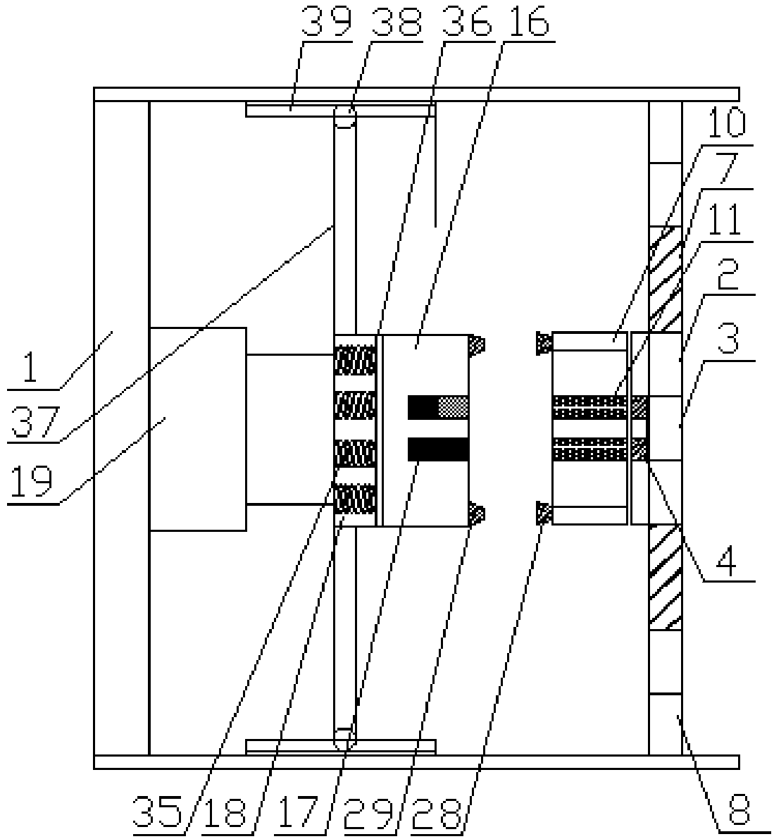
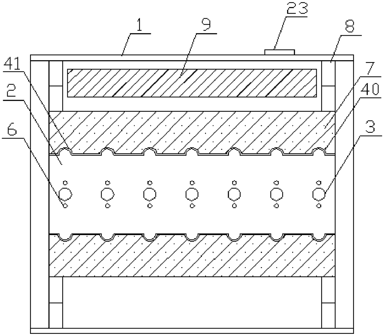
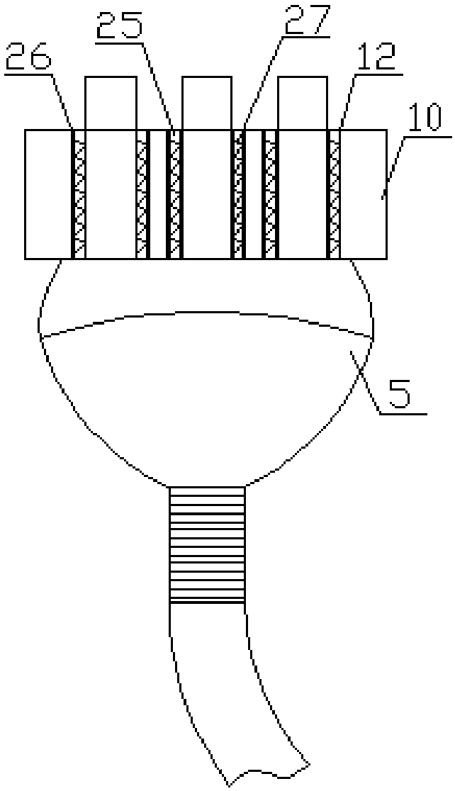
[0020] Embodiment 1: refer to Figure 1-3 , a locking device for electrical equipment, including a box body 1, a working panel 2 is arranged on the front side of the box body 1, a groove 3 is arranged on the working panel 2, and a socket 4 is arranged inside the groove 3 , the outer side of the groove 3 is provided with a plug 5, the groove 3 and the bottom are provided with an infrared sensor 6, the top and bottom of the working panel 2 are provided with a movable clamp 7, and one end of the movable clamp 7 is provided with Buckle groove 40, the edge of the movable clamp 7 and the buckle groove 40 is provided with a rubber sealing strip 41, which is conducive to clamping the plug 5, preventing the plug 5 from being easily knocked off and causing equipment shutdown and damage, and preventing water or dust from The groove 3 enters the box body 1, which affects the service life of the device and the safety of power supply. One end of the movable clamp 7 is provided with a first ...

Embodiment 2

[0023] Embodiment 2: refer to Figure 3-6 , the present invention is applied to a bridge construction equipment, comprising a box body 1, the front side of the box body 1 is provided with a working panel 2, the working panel 2 is provided with a groove 3, and the inside of the groove 3 is provided with Jack 4, the outer side of the groove 3 is provided with a plug 5, the groove 3 and the bottom are provided with an infrared sensor 6, the top and bottom of the working panel 2 are provided with a movable clamp 7, and the movable clamp 7 One end is provided with a buckle groove 40, and the edge of the movable clamp 7 and the buckle groove 40 is provided with a rubber sealing strip 41, which is conducive to clamping the plug 5, preventing the plug 5 from being easily knocked off and causing equipment shutdown and damage, and avoiding water Or dust enters the box body 1 from the groove 3, which affects the service life of the device and the safety of power supply. The first air pre...


PUM


Abstract

The invention discloses a locking device of an electric appliance. The locking device comprises a casing, the front side of the casing is provided with a work panel, the work panel is provided with grooves, each groove is internally provided with a jack, a plug is arranged outside the grooves, the top and the bottom of each groove are provided with infrared sensors respectively, the top and bottomof the work panel are provided with movable cardboards respectively, one end of each movable cardboard is provided with a first pressure bar, the inner side of the work panel is provided with a transitional connection board, and the transitional connection board is provided with through grooves. Power on / off is realized via memory alloy, the plug is clamped or loosened by utilizing the characteristic that the memory alloy expands with cold and contracts with heat, and the plug is plugged firmly and plugged in / out easily; and the infrared sensors send a signal to a PLC when it is detected thatthe distance to the hands is very near, the PLC controls the movable cardboards and a second pressure bar to work, the plug is connected with a socket and fastened, and electric shock caused by poweron by inserting the plug directly is avoided.

Description

technical field [0001] The invention relates to the field of bridge construction equipment, in particular to a locking device for electrical equipment. Background technique [0002] In the construction process of bridge construction, a large amount of electrical equipment that consumes electricity is needed. Since the plugs and sockets of existing electrical equipment are generally connected by friction fit, and no other locking devices are provided, when the staff pass by Or if other objects touch it, it is easy to knock the plug of the electrical equipment open, affecting the use of the electrical equipment. [0003] Therefore, it is necessary to invent a locking device for electrical equipment to solve the above problems. Contents of the invention [0004] The object of the present invention is to provide a locking device for electrical equipment, so as to solve the problems raised in the background art above. [0005] In order to achieve the above object, the present...

Claims


Application Information

Patent Timeline
Patent Type & Authority Applications(China)
IPC IPC(8): H01R13/629H01R13/639H01R13/66
CPCH01R13/629H01R13/6397H01R13/6683
Inventor 曹雁冰
Owner ANHUI WEIHONG STEEL STRUCTURE GRP
Why Eureka
Try Eureka