Zero-power-consumption standby energy-saving switch module with button switch

A zero-power standby and energy-saving switch technology, applied in electronic switches, electrical components, pulse technology, etc., can solve the problems of waste of electricity, standby consumption, etc., and achieve the effect of simple structure and easy button switch structure

Pending Publication Date: 2018-07-10
刘举柱
View PDF0 Cites 1 Cited by
  • Summary
  • Abstract
  • Description
  • Claims
  • Application Information

AI Technical Summary

Problems solved by technology

[0003] The technical problem to be solved by the present invention is to provide a zero-power standby energy-saving module with a button switch, which has solved the problem of standby consumption and waste of electricity when the existing household appliances and electronic products are in the standby state

Method used


Image

  • Zero-power-consumption standby energy-saving switch module with button switch

Examples


Embodiment 1

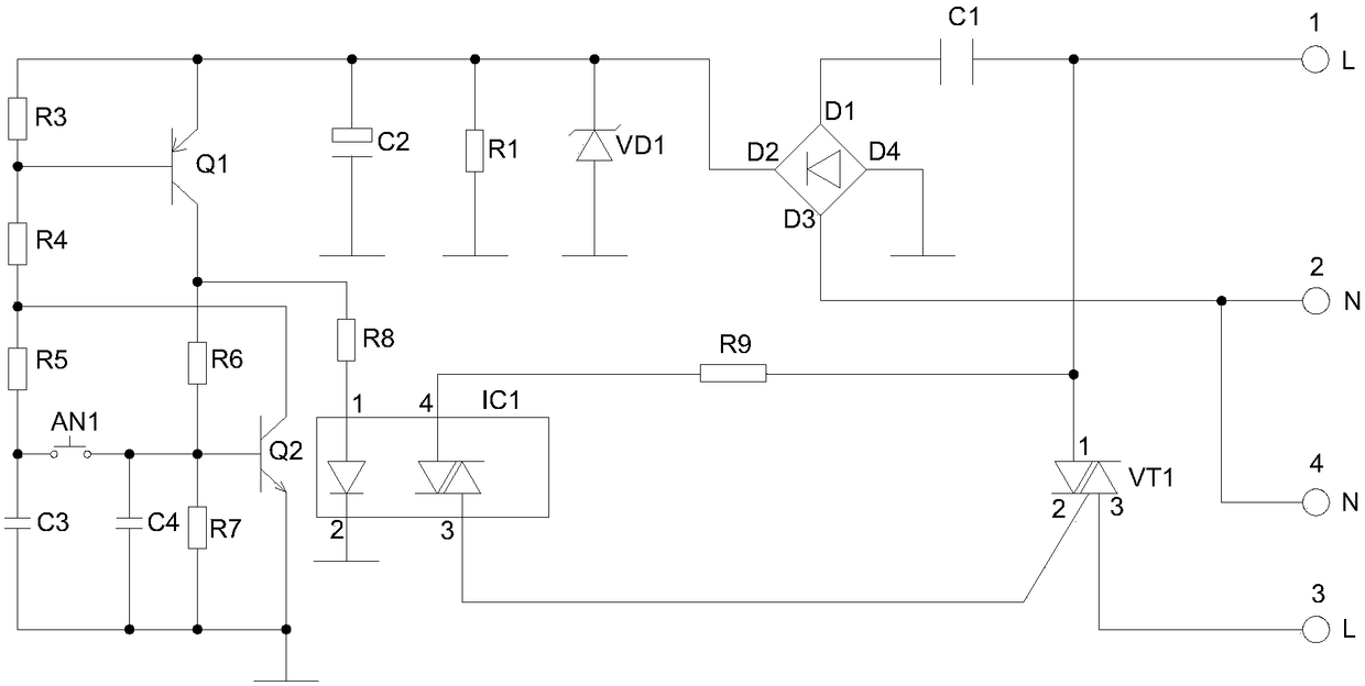
[0017] Such as figure 1 As shown, a zero-power standby energy-saving switch module with a button switch in a range hood, including terminals L1 and N2 connected to a 220V power supply, terminals N4 and L3 connected to the power input terminal of a control appliance, and a button Switch AN1, first capacitor C1, bridge rectifier, first regulator tube VD1, first resistor R1, second capacitor C2, first triode Q1, second resistor R3, third resistor R4, fourth resistor R5 , the fifth resistor R6, the sixth resistor R7, the third capacitor C3, the fourth capacitor C4, the second triode Q2, the seventh resistor R8, the photocoupler IC1, the eighth resistor R9, and the bidirectional controllable VT1.

[0018] The L1 end is respectively connected to one end of the first capacitor C1, the first pin of the triac VT1 and one end of the eighth resistor R9, and the other end of the first capacitor C1 is connected to the first connection end of the bridge rectifier. The third connecting end ...

Embodiment 2

[0025] Embodiment 2: as figure 1 As shown, a zero-power standby energy-saving switch module with a push button switch includes terminals L1 and N2 connected to a 220V power supply, terminals N4 and L3 connected to the power input terminal of a control appliance, and a button switch AN1, the first Capacitor C1, bridge rectifier, first regulator tube VD1, first resistor R1, second capacitor C2, first triode Q1, second resistor R3, third resistor R4, fourth resistor R5, fifth resistor R6 , the sixth resistor R7, the third capacitor C3, the fourth capacitor C4, the second triode Q2, the seventh resistor R8, the photocoupler IC1, the eighth resistor R9, and the bidirectional controllable VT1.

[0026] The L1 end is respectively connected to one end of the first capacitor C1, the first pin of the triac VT1 and one end of the eighth resistor R9, and the other end of the first capacitor C1 is connected to the first connection end of the bridge rectifier. The third connecting end of the...


PUM


Abstract

The invention discloses a zero-power-consumption standby energy-saving switch module with a button switch, relating to the technical field of energy-saving switches. The zero-power-consumption standbyenergy-saving switch module is characterized by comprising an L1 end and an N2 end connected to a 220V power supply, an N4 end and an L3 end connected to the power supply input end of a control electric appliance, and a button switch AN1, a first capacitor C1, a bridge rectifier, a first voltage regulator tube VD1, a first resistor R1, a second capacitor C2, a first triode Q1, a second resistor R3, a third resistor R4, a fourth resistor R5, a fifth resistor R6, a sixth resistor R7, a third capacitor C3, a fourth capacitor C4, a second triode Q2, a seventh resistor R8, a photoelectric couplerIC1, an eighth resistor R9 and a bidirectional thyristor VT1. The module disclosed by the invention is simple in structure, the button switch structure is easy to control, the control electric appliance can be rapidly turned on or turned off through the button switch, the phenomenon that the power consumption is zero when the control electric appliance is in a standby state can be achieved, the energy can be saved, and the cost can be reduced; and by connecting multiple zero-power-consumption standby energy-saving switch modules with the button switches in parallel, the function of performingmulti-cascade control on a lamp can be achieved.

Description

Technical field: [0001] The invention relates to the technical field of energy-saving switches, in particular to a zero-power standby energy-saving switch module with a button switch. Background technique: [0002] At present, when many electronic products and household appliances in our country are in standby function, there is a large standby power consumption. The electric energy consumed by electrical products in standby has become a serious energy waste. Taking household appliances as an example, there are nearly 10 kinds of household appliances with standby function in a city family, and the average monthly standby power consumption is between 15-30 watts, which accounts for about 10% of household power consumption. In other words, 10% of the electricity bill paid by a family every month is for standby power consumption. As energy saving and environmental protection become a consensus, lower standby power consumption technology is also valued by consumers. The researc...

Claims


Application Information

Patent Timeline
Patent Type & Authority Applications(China)
IPC IPC(8): H03K17/96H03K17/567
CPCH03K17/96H03K17/567H03K2217/0036
Inventor 刘举柱
Owner 刘举柱
Why Eureka
Try Eureka