Method for preventing following rotation
A technology for driving motors and driving gears, applied in the direction of DC motor speed/torque control, electrical components, control systems, etc., can solve the problems of large current at the moment of commutation and rotation of the driving motor, inability to realize double-rotation grilling, etc., to improve grilling. The effect of uniformity, energy saving, power consumption and cost reduction
- Summary
- Abstract
- Description
- Claims
- Application Information
AI Technical Summary
Problems solved by technology
Method used
Image
Examples
Embodiment 1
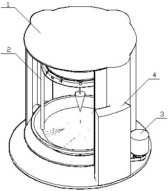
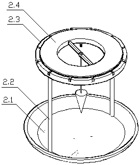
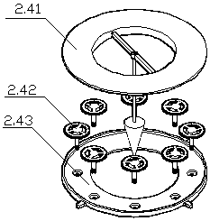
[0014] see Figure 1-Figure 5 , this embodiment includes an annular cooking chamber 1, a double rotating grill 2, a drive motor 3, and an electric control device 4. The grill 2 includes a chassis 2.1, a column 2.2, an upper beam 2.3, and a combined carrier 2.4, wherein the combined carrier The tool includes an annular upper cover 2.41, a drive gear 2.42 and a lower cover 2.43. The outer side of the inner wall 2.412 of the annular upper cover 2.41 is provided with teeth that engage with the above-mentioned drive gear 2.42, and are used for rotating the drive gear 2.42 with the grill 2. When making it rotate around its own axis, the inner side of the inner wall 2.412 of the annular upper cover 2.41 is provided with a counterweight beam 2.413, and a drooping counterweight 2.414 is provided at the center of the beam for increasing the upper cover When grilling, the electric control device 4 changes the running speed of the drive motor 3 in good time, so that the grill 2 can get ri...
Embodiment 2
[0016] Compared with Embodiment 1, the difference between this embodiment and Embodiment 1 is that R1 in Embodiment 1 is replaced by a non-contact Hall current sensor HS1. The function of R1 is to convert the load current into a voltage signal that is convenient for sampling. It is a dilemma. The small resistance value sampling voltage dynamic range is too small, and the large resistance value is not conducive to voltage stabilization and speed reduction, and is not conducive to reducing energy consumption. The Hall current sensor HS1 is composed of the power line of the drive motor 3 and the induction The coil is formed by co-winding a magnetic core, and the sampling signal is an induced current. Using it instead of R1 has the advantages of a wide dynamic range of the sampling signal and no power consumption. All the rest are the same as in Example 1.
PUM
 Abstract
Description
Claims
Application Information
 - R&D
- Intellectual Property
- Life Sciences
- Materials
- Tech Scout
- Unparalleled Data Quality
- Higher Quality Content
- 60% Fewer Hallucinations
Browse by: Latest US Patents, China's latest patents, Technical Efficacy Thesaurus, Application Domain, Technology Topic, Popular Technical Reports.
© 2025 PatSnap. All rights reserved.Legal|Privacy policy|Modern Slavery Act Transparency Statement|Sitemap|About US| Contact US: help@patsnap.com


