Frostless air source cascade heat pump steam generator and operation method thereof

A technology of steam generator and evaporator, which is applied in the field of waste heat recovery, which can solve the problems that the unit cannot work normally, it is difficult to apply the heat pump system, and the heat supply of the unit is reduced, so as to overcome low energy efficiency and intermittent heating operation, and improve area utilization rate and heat transfer efficiency, the effect of reducing carbon dioxide emissions

Pending Publication Date: 2022-06-07
JIANGSU UNIV OF SCI & TECH
View PDF0 Cites 0 Cited by
  • Summary
  • Abstract
  • Description
  • Claims
  • Application Information

AI Technical Summary

Problems solved by technology

Air source heat pump is a high-energy-efficiency system, but when the system is running in winter, frost will form on the surface of the outdoor heat exchanger. The frost layer not only increases the heat transfer resistance between the heat exchanger and the air, but also makes the air The flow resistance increases and the flow decreases, which reduces the heat supply of the unit, and even causes the unit to fail to work normally; the most commonly used defrosting methods are reverse cycle hot gas defrosting or hot gas bypass defrosting, but these methods will cause the heat pump to intermittently work, and high defrosting energy consumption, it is difficult to apply to the occasions where the ambient temperature is low in winter and the heat pump system needs to work continuously
In addition, when the heat pump is used for steam generation, an efficient steam generation heat exchanger is the key. The traditional method of hot water circulation plus flash evaporator and gas-liquid separator requires a large investment in equipment and is not competitive in the market.

Method used


Image

  • Frostless air source cascade heat pump steam generator and operation method thereof

Examples


Embodiment Construction

[0026] In order to make the above objects, features and advantages of the present invention more clearly understood, the technical solutions of the present invention will be further described in detail below with reference to the accompanying drawings and embodiments.

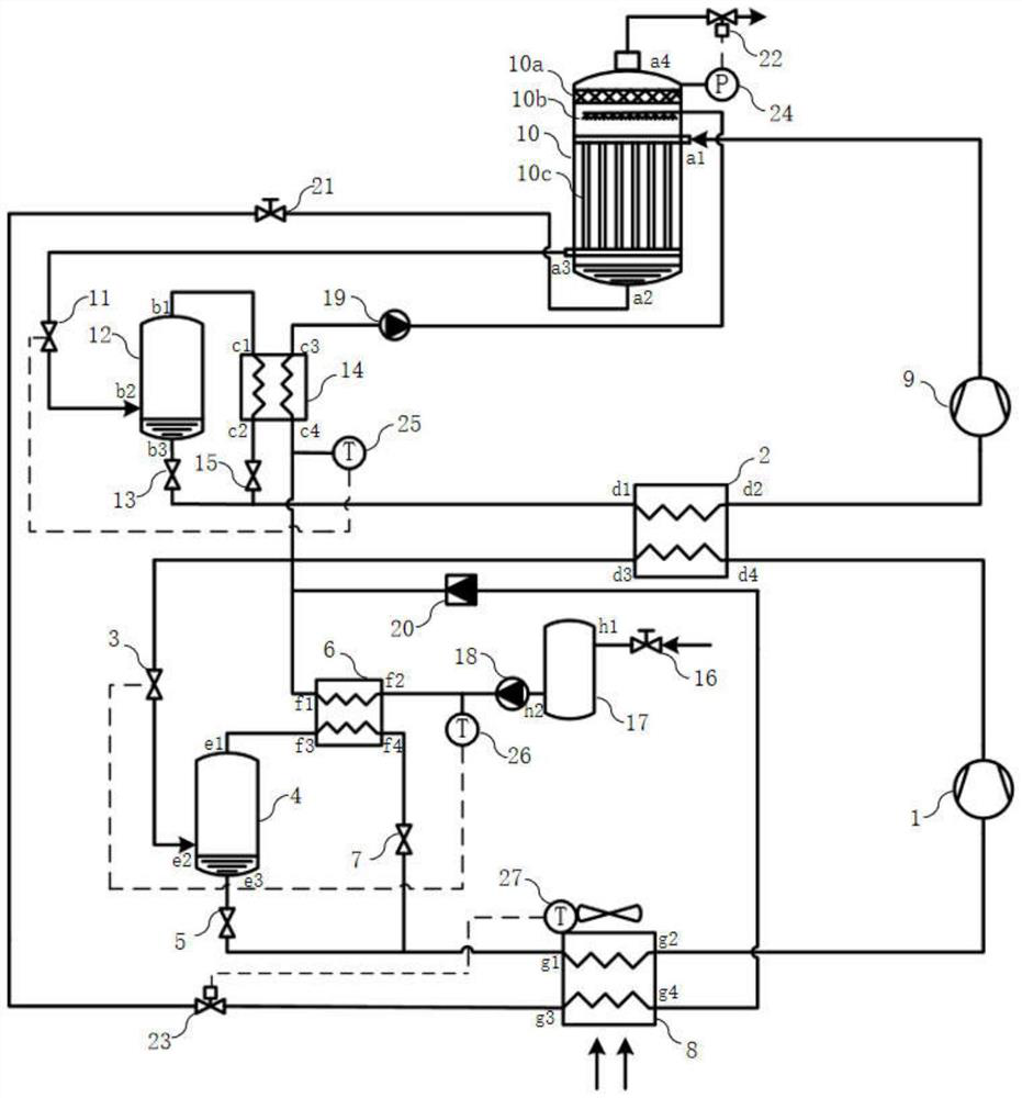
[0027] like figure 1 Shown: it is a frost-free air source cascade heat pump steam generator of the present invention, which includes a low temperature level circulation system, a high temperature level circulation system and a water system.

[0028] The low temperature stage circulation system includes: a first compressor 1, an evaporative condenser 2, a first throttle valve 3, a first gas-liquid separator 4, a second throttle valve 5, a first preheater 6, a third Throttle valve 7 and air source evaporator 8, the outlet of the first compressor 1 is connected to the lower inlet d4 of the evaporative condenser 2, and the lower outlet d3 of the evaporative condenser 2 is connected to the first air through the firs...


PUM


Abstract

The invention discloses a frostless air source heat pump steam generator which comprises a low-temperature-level circulation system, a high-temperature-level circulation system and a water system, an evaporator of the low-temperature-level circulation system is an air source evaporator with a water heat exchange pipeline arranged on the air inlet side, and the low-temperature-level circulation system is connected with the high-temperature-level circulation system through an evaporative condenser. Refrigerant gas of the high-temperature-stage circulating system is evaporated through spraying water outside a heating pipe of the vertical shell and tube heat exchanger to generate water vapor; refrigerant liquid of the low-temperature-stage circulating system and refrigerant liquid of the high-temperature-stage circulating system are subjected to primary throttling and gas-liquid separation firstly, refrigerant gas generated after throttling is used for heating make-up water, and the liquefied refrigerant liquid and separated liquid are throttled again and then enter the corresponding evaporators to absorb heat and evaporate. The air source heat pump and the efficient steam generation heat exchanger are combined, and the problems of frosting and defrosting of the air source evaporator in winter can be effectively solved while it is guaranteed that the steam supply amount is sufficient.

Description

technical field [0001] The invention belongs to the technical field of waste heat recovery, and in particular relates to a frost-free air source cascade heat pump steam generator and an operation method thereof. Background technique [0002] As a common production medium and heat carrier in industrial production, steam is widely used in printing and dyeing, chemical industry and other fields. Necessary measures for enterprises to reduce costs, protect the environment, and improve energy efficiency. At present, enterprises generally use boilers or electric heaters to directly heat water to generate steam, but the use of boilers will emit a large amount of carbon dioxide, which is not in line with my country's green development policy. [0003] Compared with boilers and electric heating, the most prominent advantage of heat pump technology is that it consumes a small amount of electricity, that is, it can convert low-grade heat into high-grade heat, thereby obtaining a large am...

Claims


Application Information

Patent Timeline
Patent Type & Authority Applications(China)
IPC IPC(8): F22B1/02F22B35/00F25B7/00
CPCF22B1/02F22B35/00F25B7/00Y02P80/15
Inventor 沈九兵周子晗王炳东骆礼梅
Owner JIANGSU UNIV OF SCI & TECH
Why Eureka
Try Eureka