Building concrete conveyor

A concrete and conveyor technology, which is applied in clay preparation devices, mixing operation control, mixing plants, etc., can solve the problems of wasting manpower, low conveying efficiency, and high usage limitations, and achieves improving usage limitations, shortening conveying cycles, and improving The effect of conveying efficiency

Inactive Publication Date: 2018-07-13
山西云度知识产权服务有限公司
View PDF7 Cites 5 Cited by
  • Summary
  • Abstract
  • Description
  • Claims
  • Application Information

AI Technical Summary

Problems solved by technology

[0002] As we all know, the concrete conveyor for construction is a kind of auxiliary device used for conveying concrete in the process of building pouring, so that the concrete can be transported to the required pouring place faster, and it has been widely used in the field of house construction; The concrete conveyor for construction includes a hopper, a hopper, a delivery pump and a delivery pipe. The hopper is located at the upper end of the hopper, and the bottom of the hopper is connected to the top of the hopper, and the hopper communicates with the inside of the hopper, and the bottom of the hopper There is a discharge port, the input end of the delivery pump is connected with the feed port, and the output end of the delivery pump is connected with the delivery pipe; when the existing concrete conveyor for construction is used, the mixed concrete is first manually put into the hopper, and then Just turn on the delivery pump and deliver the concrete to the required concrete location through the delivery pipe; in the existing use, it is found that the concrete needs to be mixed in advance, which leads to a longer delivery period of the concrete conveyor for construction and lower delivery efficiency; and the material needs to be manually Putting into the hopper wastes manpower and has high limitations in use

Method used


Image

  • Building concrete conveyor
  • Building concrete conveyor
  • Building concrete conveyor

Examples


Embodiment Construction

[0021] The specific implementation manners of the present invention will be further described in detail below in conjunction with the accompanying drawings and embodiments. The following examples are used to illustrate the present invention, but are not intended to limit the scope of the present invention.

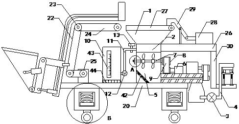
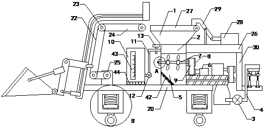
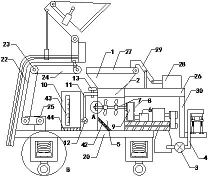
[0022] Such as Figure 1 to Figure 6 Shown, a kind of construction concrete conveyer of the present invention comprises hopper 1, hopper 2, conveying pump 3 and conveying pipe 4, and hopper is positioned at the upper end of hopper, and the top end of hopper is connected with the top of hopper, and The hopper is communicated with the inside of the material box, and the bottom of the material box is provided with a discharge port; including the mixing box 5, the stirring motor 6, the stirring shaft 7, the driven belt shaft 8, the belt 9, the water tank 10 and the water delivery pipe 11, and the mixing box is located at Below the material box, there is a stirring chamber ins...


PUM


Abstract

The invention relates to the technical field of house construction pouring accessory devices, in particular to a building concrete conveyor. According to the conveyor, automatic material mixing can beachieved, the conveying period can be shortened, conveying power is improved, automatic material putting is achieved, manpower is little, and use limitation is improved; the conveyor comprises a hopper, a material box, a conveying pump and a conveying pipe; a stirring box, a stirring motor, a stirring shaft, a driven belt shaft, a belt, a water tank and a water feeding pipe are included; the stirring box is located below the material box, the output end of the conveying pump is communicated with the input end of the conveying pipe, the water tank is located on the left side of the stirring box, the water feeding pipe is provided with a water feeding pump and a water feeding valve, a tipping bucket, a tipping bucket hydraulic cylinder, a receiving hydraulic cylinder, a first connecting rod, a rocker arm rod, a sliding support, a connecting plate and a chain transmission device are included, guide rails are arranged on outer walls of steel beams, on the front side and the rear side, ofthe sliding support, the right end of the first connecting rod and the right end of the receiving hydraulic cylinder are provided with sliding blocks, the sliding blocks are in sliding fit with the guide rails, and the chain transmission device is located below the sliding support.

Description

technical field [0001] The invention relates to the technical field of building construction pouring accessories, in particular to a concrete conveyor for construction. Background technique [0002] As we all know, the concrete conveyor for construction is a kind of auxiliary device used for conveying concrete in the process of building pouring, so that the concrete can be transported to the required pouring place faster, and it has been widely used in the field of house construction; The concrete conveyor for construction includes a hopper, a hopper, a delivery pump and a delivery pipe. The hopper is located at the upper end of the hopper, and the bottom of the hopper is connected to the top of the hopper, and the hopper communicates with the inside of the hopper, and the bottom of the hopper There is a discharge port, the input end of the delivery pump is connected with the feed port, and the output end of the delivery pump is connected with the delivery pipe; when the exi...

Claims


Application Information

Patent Timeline
Patent Type & Authority Applications(China)
IPC IPC(8): B28C5/14B28C7/08B28C7/16B28C9/04
CPCB28C5/14B28C7/0858B28C7/167B28C9/04
Inventor 李有花
Owner 山西云度知识产权服务有限公司
Why Eureka
Try Eureka