Double flow type fresh air purification device

A purification device and double-flow technology, which is applied in ventilation system, heating method, space heating and ventilation, etc., can solve the problems of high renovation cost and large space occupation, so as to improve aesthetics, reduce space occupation, and reduce costs Effect

Inactive Publication Date: 2018-07-13
QINGDAO HAIER AIR CONDITIONER GENERAL CORP LTD
View PDF5 Cites 4 Cited by
  • Summary
  • Abstract
  • Description
  • Claims
  • Application Information

AI Technical Summary

Problems solved by technology

[0005] In order to solve the above-mentioned problems in the prior art, that is, in order to solve the problems of the existing fresh air system using prismatic heat exchange cores that occupy a large space and have high renovation costs, the present invention provides a double-flow fresh air purification device. The double-flow fresh air purification device includes a two-way inlet and outlet air duct, an air intake system and an exhaust system, and the two-way inlet and outlet air duct includes an outer tube and a first inner tube and a second inner tube arranged in the outer tube. A heat exchange core is arranged in the outer tube, and the heat exchange core divides the outer tube into a first part and a second part, and the first inner tube and the second inner tube are located between the first part and the second inner tube respectively. The second part, the air intake system includes the second part of the outer tube, the heat exchange core, the induced fan and the first inner tube according to the air flow direction, and the induced fan is installed in the first inner tube The air intake system is set to be able to introduce the outdoor fresh air into the double-flow fresh air purification device through the second part of the outer pipe under the drive of the induced draft fan and pass through the heat exchange core. The first inner tube is introduced into the room; the exhaust system includes the first part of the outer tube, the heat exchange core, the exhaust fan and the second inner tube according to the air flow direction, and the exhaust fan is installed on the The second inner pipe, the exhaust system is set to be able to introduce indoor air through the first part of the outer pipe into the double-flow fresh air purification device and pass through the heat exchange core under the drive of the exhaust fan After heat exchange with the fresh air introduced by the air intake system, it is discharged to the outside through the second inner pipe

Method used


Image

  • Double flow type fresh air purification device
  • Double flow type fresh air purification device
  • Double flow type fresh air purification device

Examples


Embodiment 1

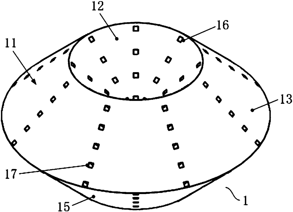
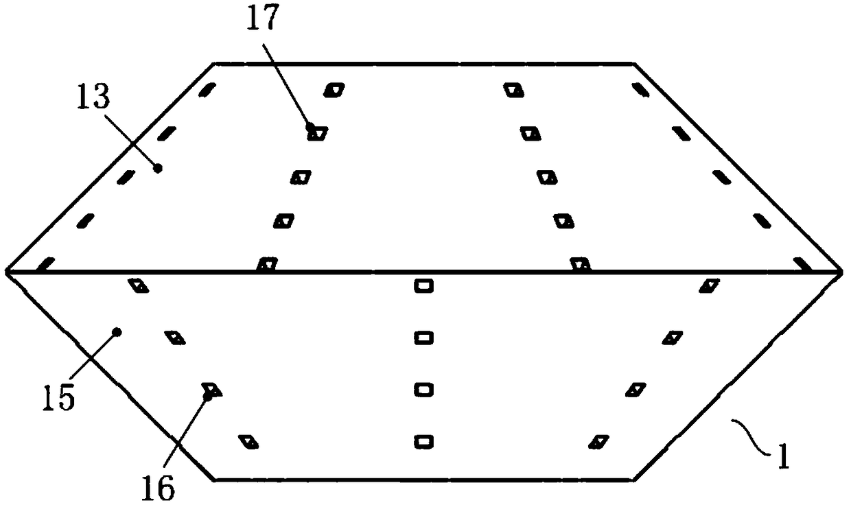
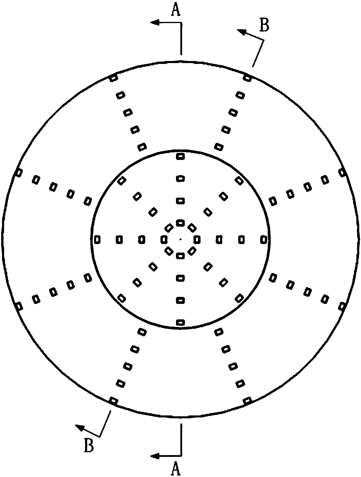
[0043] First refer to Figure 1 to Figure 6 , to describe the first embodiment of the heat exchange core used in the two-way inlet and outlet air ducts of the present invention. in, figure 1 It is a structural schematic diagram of the heat exchange core used for the two-way inlet and outlet air ducts in the first embodiment of the present invention; figure 2 It is the front view of the heat exchange core used for the two-way inlet and outlet air ducts in the first embodiment of the present invention; image 3 It is a top view of the heat exchange core used for the two-way inlet and outlet air ducts in the first embodiment of the present invention; Figure 4 for image 3 Sectional view along A-A direction; Figure 5 for image 3 Sectional view along B-B direction; Figure 6 It is a structural schematic diagram of the heat exchanger in the first embodiment of the present invention.

[0044] Such as Figure 1 to Figure 6 As shown, the present invention firstly provides a...

Embodiment 2

[0053] Refer below Figure 8 to Figure 12 , to describe the second embodiment of the heat exchange core used in the two-way inlet and outlet air ducts of the present invention. in, Figure 8 It is a structural schematic diagram of the heat exchange core used for the two-way inlet and outlet air ducts in the second embodiment of the present invention; Figure 9 It is the front view of the heat exchange core used for the two-way inlet and outlet air ducts in the second embodiment of the present invention; Figure 10 for Figure 9 Sectional view along C-C direction; Figure 11 for Figure 9 Sectional view along D-D direction; Figure 12 It is a structural schematic diagram of the heat exchanger in the second embodiment of the present invention.

[0054] Such as Figure 8 to Figure 12 As shown, the present invention also provides a heat exchange core 3 for a two-way inlet and outlet air duct 4, the two-way inlet and outlet air duct 4 includes an outer tube 41 and a first in...

Embodiment 3

[0061] Refer below Figure 13 to Figure 16 , the dual-flow fresh air purification device of the present invention is described. in, Figure 13 It is a structural schematic diagram (without draft tube) of the dual-flow fresh air purification device of the present invention; Figure 14 It is a schematic diagram of the working principle of the dual-flow fresh air purification device of the present invention (without draft tube); Figure 15 It is a schematic structural view of the dual-flow fresh air purification device of the present invention (there is a draft tube); Figure 16 It is a schematic diagram of the working principle of the dual-flow fresh air purification device of the present invention (with a draft tube).

[0062] Such as Figure 13 and Figure 14 As shown, the dual-flow fresh air purification device 5 of the present invention (hereinafter referred to as the purification device 5) mainly includes a two-way air inlet and outlet duct, an air intake system and an...


PUM


Abstract

The invention relates to the field of air conditioning, in particular to a double flow type fresh air purification device. The double flow type fresh air purification device provided by the inventionaims to solve the problem that existing fresh air systems are large in occupied space and high in improvement cost. In order to achieve the purpose, the double flow type fresh air purification devicecomprises a bidirectional air inlet-outlet pipe, an air inlet system and an exhaust system, wherein the bidirectional air inlet-outlet pipe comprises an outer tube, and a first inner tube and a secondinner tube arranged in the outer tube, a heat exchange core is arranged in the outer tube, the heat exchange core divides the outer tube into a first part and a second part, and the first inner tubeand the second inner tube are separately located in the first part and the second part; the air inlet system comprises a second part of the outer tube, the heat exchange core, an bidirectional air inlet-outlet pipe and a first inner tube along the air flowing direction; the exhaust system comprises a first part of the outer tube, the heat exchange core, an exhaust fan and the second inner tube along the air flowing direction. By arranging the heat exchange cores, spaced occupied by the heat exchange cores in the purification device can be reduced, and the mounting and improving costs are lowered.

Description

technical field [0001] The invention relates to the field of air conditioning, in particular to a double-flow fresh air purification device. Background technique [0002] The air pollution report released by the International Energy Agency clearly mentioned that as many as 97% of Chinese people are exposed to the harm of PM2. The cardiopulmonary immunity of people in heavy smog areas has dropped by 10%. In recent years, due to the intensification of air pollution and frequent smog, people cannot often open windows for ventilation. As a result, bacterial particles such as PM2.5 in the indoor air can easily invade the lungs and respiratory tract, causing cough, asthma, pneumonia and even lung cancer. At the same time, it also causes cross-infection among people, which is regarded as the root cause of respiratory epidemics. In addition, people stay in a closed indoor environment for a long time, and the decoration pollutants such as formaldehyde and TVOC and the carbon dioxid...

Claims


Application Information

Patent Timeline
Patent Type & Authority Applications(China)
IPC IPC(8): F24F3/16F24F7/10F24F13/30F24F8/10F24F8/167
CPCF24F3/16F24F7/10F24F13/30F24F8/167F24F8/10F24F12/006F24F13/28F24F2221/34F28D21/0008F28F7/02Y02B30/56F24F8/15F24F8/30
Inventor 刘光朋
Owner QINGDAO HAIER AIR CONDITIONER GENERAL CORP LTD
Why Eureka
Try Eureka