
Method for quickly measuring angles of flange holes

A flange hole, fast technology, applied in the direction of angle/taper measurement, etc., can solve the problems of inappropriate economy or efficiency, large error in marking measurement, easy to scratch the surface of parts, etc., to achieve easy operation, improve accuracy, Easy-to-use effects

Pending Publication Date: 2018-07-13
CHENGDU AIRCRAFT INDUSTRY GROUP
View PDF0 Cites 5 Cited by
  • Summary
  • Abstract
  • Description
  • Claims
  • Application Information

AI Technical Summary

Problems solved by technology

Another method is to manually draw the connecting line on the center of the flange hole with a straightedge marking tool, and then measure the angle between the connecting lines of two adjacent holes with an angle ruler to determine the angle between the axis of the hole. The distribution angle between the flange holes is detected by detection. This detection method is affected by whether the inspector can clamp the vernier caliper during the operation, and the error has a great impact. When detecting the position of two adjacent holes, the number of detections is large. Affect work efficiency
The disadvantage of this method is that it is easy to scratch the surface of the part and the measurement accuracy is not high due to the large measurement error of the scribing line
The above method is obviously inappropriate in terms of economy and efficiency.

Method used


Image

  • Method for quickly measuring angles of flange holes
  • Method for quickly measuring angles of flange holes
  • Method for quickly measuring angles of flange holes

Examples


Embodiment Construction

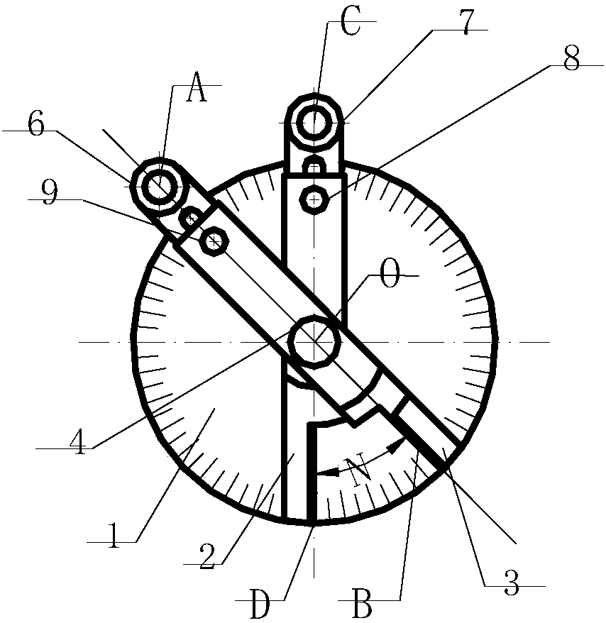
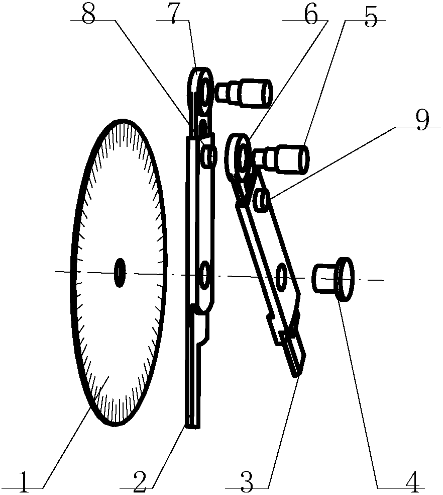
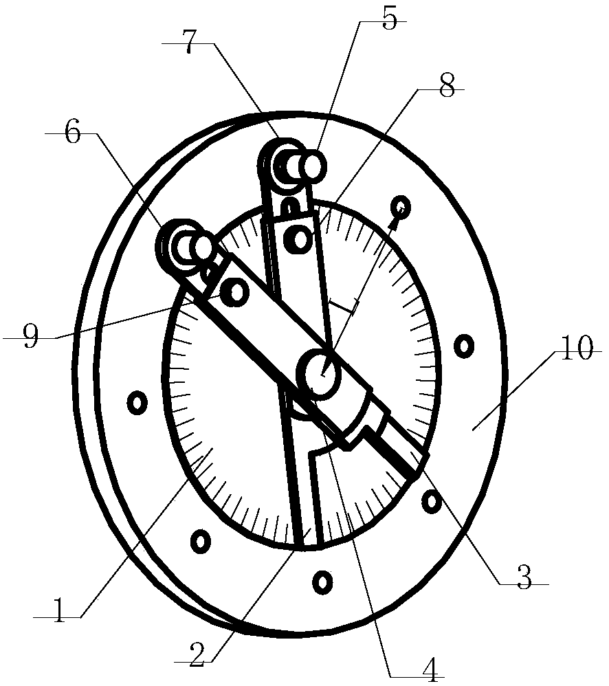
[0017] refer to Figure 1-Figure 3 . According to the present invention, first, according to the distance L between the flange hole of the part 10 to be inspected and the flange center point as the radius, an angle plate 1 with a measuring scale is made with a size smaller than the distance L, and an angle plate 1 is made on the axis of the angle plate 1. Rotate around the central hole O axis of the rotating shaft 4, the main angle ruler 2 and the auxiliary angle ruler 3 that are cross-connected, wherein, the same side radial direction of the main angle ruler 2 and the auxiliary angle ruler 3 are shaped with opposite symmetrical L-shaped notches, and the L-shaped notch sides D, The extension line of the L-shaped notch side B passes through the central hole O and the hole system plunger positioning hole A on the opposite end, and the center of the hole system plunger dynamic measurement hole C is on a straight line, forming a scissors differential rotation pair; two shapes The...


PUM


Abstract

The invention discloses a method for quickly measuring angles of flange holes and aims to realize freeness of site limitation, convenience in operation, accuracy in positioning and high detection accuracy of a method for quickly measuring angles of uniformly distributed holes of parts such as flanges. The technical scheme for implementation includes that an angle scale with measurement scales is made according to a flange radius and a size smaller than a flange hole distance L, a main angle ruler and an auxiliary angle ruler are made on the angle scale and in rotational cross connection aroundthe axis of a rotating shaft center hole O, same sides of the main angle ruler and the auxiliary angle ruler are radially provided with L-shaped notches symmetrical in opposite directions, and an extension connection line of each L-shaped notch and a circle center of a corresponding hole plunger positioning hole in an opposite end are collinear through the center hole O to form a scissors difference rotating pair; two hole plunger bolts identical in shape and size are inserted into to-be-tested flange holes through the hole plunger positioning holes, and a value of an angle between the auxiliary angle ruler and the main angle ruler is read out to obtain an included angle between the two to-be-tested flange holes of a flange face.

Description

technical field [0001] The invention relates to a method for detecting the angular size of uniformly distributed holes in the circumferential direction of mechanical flange parts and a general auxiliary detection tool for detecting the angular size. technical background [0002] In the manufacturing process of the machinery industry, the flange is a disc-shaped part, and the flange is also called a flange, which is used in pairs. The flange is mainly used for the connection of pipelines, and is most common in boiler and pipeline engineering. Flange is one of the most widely used parts in industry, and its production volume is relatively large. At the joints of the pipelines that need to link, it is usually necessary to install a flange. deficient-pressure pipelines can use wire flanges and welding flanges with pressures greater than 4 kg. Add seals between the two flanges, and then tighten with bolts. Flanges with different pressures have different thicknesses and use diff...

Claims


Application Information

Patent Timeline
Patent Type & Authority Applications(China)
IPC IPC(8): G01B5/24
CPCG01B5/24
Inventor 徐龙梅颖栾丽王宏黄吉传
Owner CHENGDU AIRCRAFT INDUSTRY GROUP
Learn More