Optical phase difference demodulation method based on spiral interference image feature extraction technology

An interference image and optical phase technology, applied in the field of applied optics, can solve the problems of high price and large size of the spectrometer, and achieve the effect of facilitating feature extraction and improving efficiency

Inactive Publication Date: 2018-07-13
NORTHEASTERN UNIV
View PDF6 Cites 2 Cited by
  • Summary
  • Abstract
  • Description
  • Claims
  • Application Information

AI Technical Summary

Problems solved by technology

However, in spectrum measurement, a spectrum analyzer is indispensable. At present, the spectrometer is large in size and expensive

Method used


Image

  • Optical phase difference demodulation method based on spiral interference image feature extraction technology
  • Optical phase difference demodulation method based on spiral interference image feature extraction technology
  • Optical phase difference demodulation method based on spiral interference image feature extraction technology

Examples


Embodiment 1

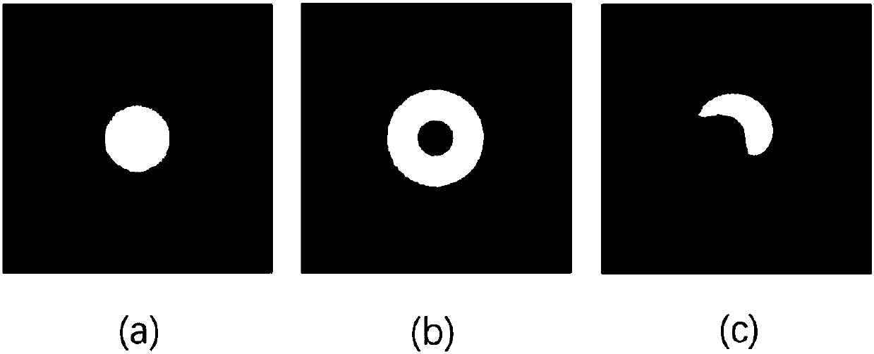
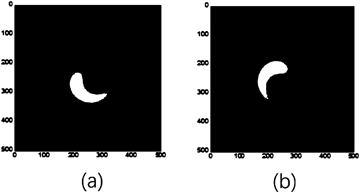
[0055] Such as figure 1 As shown, the spiral interference image ( figure 1 c) by a Gaussian beam ( figure 1 a) and an orbital angular momentum beam ( figure 1 b) Interference formation. In this embodiment, the size of the spiral interference image is 500×500, and in the spiral interference image ( figure 1 c) There are spiral-shaped stripes.

[0056] The topological charge of the orbital angular momentum beam is +1. ( figure 1 b).

[0057] The topological charge of the Gaussian beam is 0, and the light intensity distribution of the Gaussian beam along the radial direction satisfies the Gaussian function ( figure 1 a).

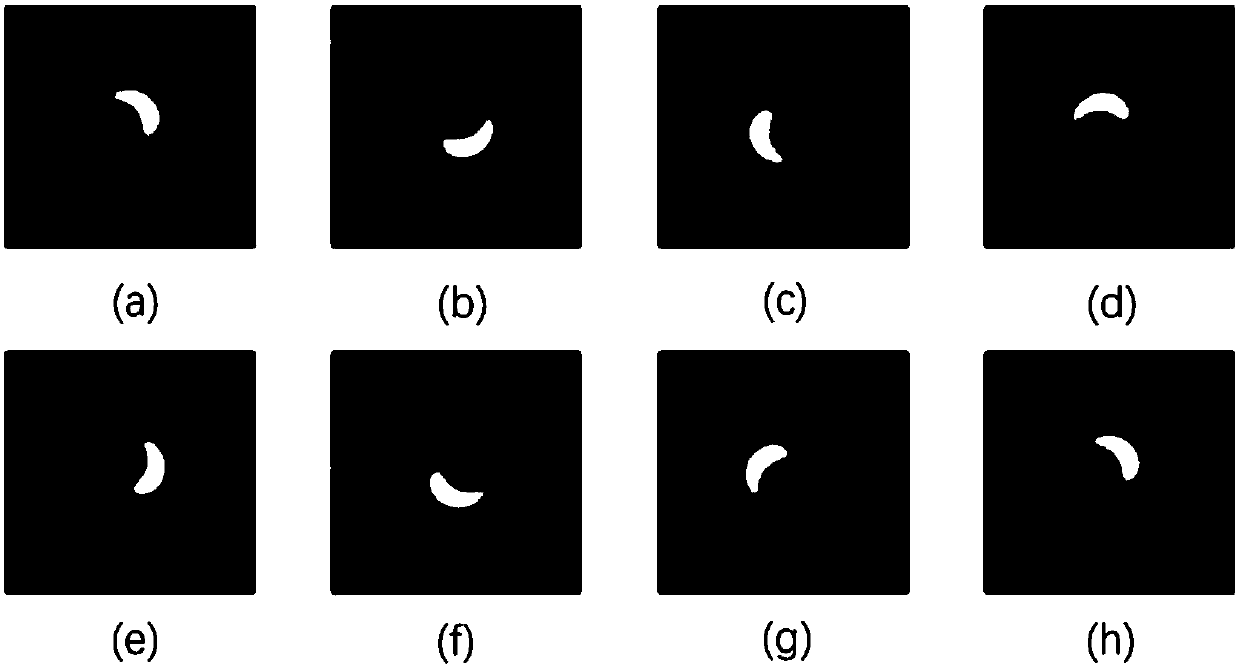
[0058] Such as figure 2 As shown, there are 32 spiral interference images used to extract the common feature image in this embodiment, the corresponding optical phase difference range is 0 degrees to 360 degrees, and the interval of optical phase difference changes is 11.25 degrees. figure 2 Eight helical interferograms out of 32 helical interferogr...


PUM


Abstract

The invention provides an optical phase difference demodulation method based on a spiral interference image feature extraction technology. The method can be used for demodulating optical phase differences between two light beams. The method includes the steps: acquiring spiral interference images formed by interference of orbit angle momentum light beams and Gaussian light beams; extracting commonfeature images for analyzing a series of spiral interference images corresponding to different optical phase differences to obtain the common feature images of the spiral interference images; demodulating features, mapping the spiral interference images to two-dimensional space taking the common feature images as base vectors, and calculating coordinate values of the spiral interference images inthe two-dimensional space to achieve data dimension reduction of the spiral interference images; calculating the optical phase differences by the coordinate values in the two-dimensional space. According to the method, feature extraction is facilitated by the spiral interference images, data dimension reduction of the spiral interference images is performed, so that signal demodulating efficiencyis improved, and the influence of power fluctuation of the light beams on demodulating results of the optical phase differences can be effectively avoided.

Description

technical field [0001] The invention relates to the field of applied optics, in particular to an optical phase difference demodulation method based on a spiral interference image feature extraction technology. Background technique [0002] With the increasing demand for information, optical inspection technology has attracted widespread attention due to its high-precision measurement performance. Optical interferometer is an optical detection instrument that uses the interference effect of light to obtain the physical quantity to be measured. Optical interferometer is used in many precision measurement fields such as astronomy, optics, engineering measurement, oceanography, seismology, spectral analysis, quantum physics, etc. widely used. Signal demodulation methods commonly used in optical interferometers include intensity demodulation and wavelength demodulation. In comparison, the intensity demodulation method is more intuitive, its structure is simple and its cost is l...

Claims


Application Information

Patent Timeline
Patent Type & Authority Applications(China)
IPC IPC(8): G01J3/00
CPCG01J3/00
Inventor 胡海峰李泽华朱思琦
Owner NORTHEASTERN UNIV
Why Eureka
Try Eureka