Reconfigurable tightly-coupled wideband array antenna

An array antenna and tight coupling technology, which is applied in the direction of slot antenna, antenna grounding device, radiation element structure, etc., can solve the problem of inability to achieve full coverage performance, and achieve the effect of widening the bandwidth

Active Publication Date: 2018-07-13
XIAN XINGWANG ANTENNA TECH +2
View PDF8 Cites 9 Cited by
  • Summary
  • Abstract
  • Description
  • Claims
  • Application Information

AI Technical Summary

Problems solved by technology

However, with the deepening of research and the increase of engineering application requirements, the tightly coupled antenna array is also limited by the structural problems of the feed balun and the impact of performance degradation at both ends of the frequency band, so it is impossible to achieve S / C / X / Full coverage of Ku band and excellent performance in this band

Method used


Image

  • Reconfigurable tightly-coupled wideband array antenna
  • Reconfigurable tightly-coupled wideband array antenna
  • Reconfigurable tightly-coupled wideband array antenna

Examples


Embodiment Construction

[0027] The present invention will be described in further detail below in conjunction with the accompanying drawings and specific embodiments.

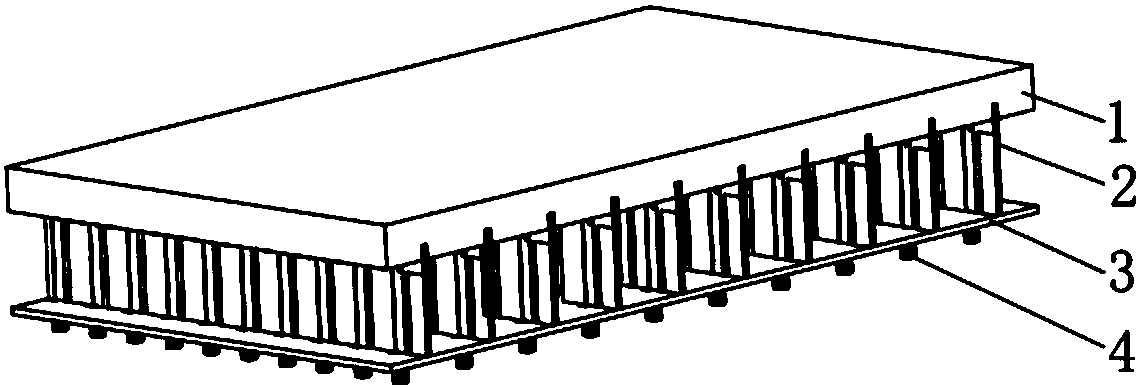
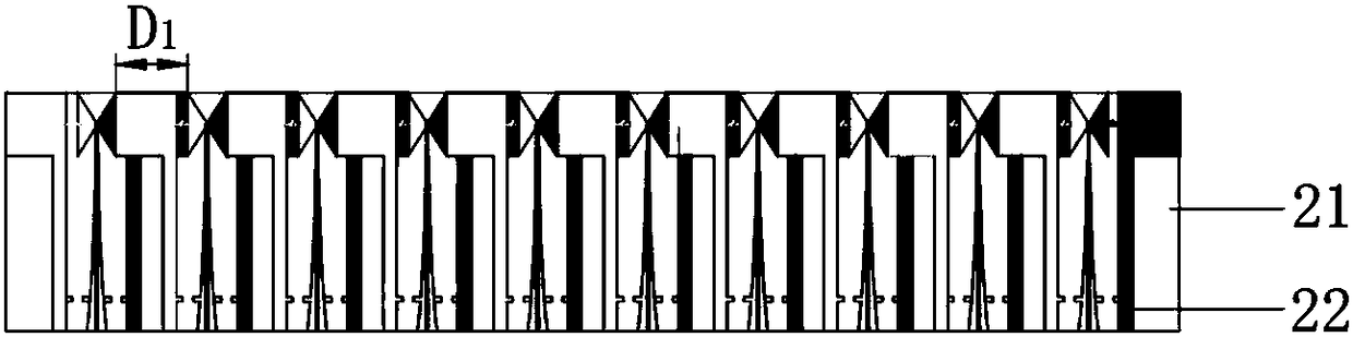
[0028] refer to figure 1 , a reconfigurable tightly coupled broadband array antenna, including a dielectric wide-angle matching plate 1 and a metal floor 3 arranged in parallel up and down, and M periodic The dipole antenna boards 2 arranged in parallel have M≧2. In this embodiment, M is set to 10 to meet the actual bandwidth requirements while taking into account miniaturization.

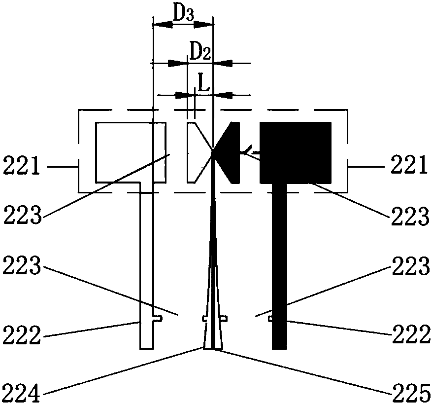
[0029] The metal floor 3 has a length of 119.28mm, a width of 224mm, and a height of 0.5mm. There are 10 rows of 10 rectangular through-holes in each row, and the row spacing is 22.4mm. The rectangular through holes on each row The spacing between the through holes is 11.2 mm, the length is 2 mm, and the width is 0.6 mm, so that when the balun ground wire 224 is grounded and the balun core wire 225 is connected to the corresponding antenna connector 4 fix...


PUM


Abstract

The invention provides a reconfigurable tightly-coupled wideband array antenna used for solving the technical problem of array antenna bandwidth limitation. The reconfigurable tightly-coupled widebandarray antenna comprises a dielectric wide-angle matching plate, a metal ground plate and M dipole antenna plates, the dielectric wide-angle matching plate and the metal ground plate are in vertical parallel arrangement, and the dipole antenna plates are in periodic arrangement and vertically fixed between the dielectric wide-angle matching plate and the metal ground plate. Each dipole antenna plate comprises a dielectric plate and N dipole radiation units in periodic arrangement. Antenna arms of every two adjacent dipole radiation units are overlapped, and each antenna arm comprises a front arm and a rear arm, wherein in every two adjacent dipole radiation units, one front arm is connected with a ground wire of a balance converter while the other front arm is connected with a core wire ofthe balance converter, the core wire of the balance converter is connected with an antenna connector fixed to the metal ground plate, and the two rear arms are connected with the metal ground plate through short-circuit balance stubs. Switches are connected between the front arms and the rear arms of every two adjacent antenna arms and between the ground wire of the balance converter and the twoshort-circuit balance stubs respectively, and through on and off of the switches, switching between a tight coupling mode and a conventional mode is realized, and full coverage of S/C/X/Ku frequency bands is realized.

Description

technical field [0001] The invention belongs to the technical field of antennas, and relates to an array antenna, in particular to a reconfigurable tightly coupled broadband array antenna covering S / C / X / Ku frequency bands. Background technique [0002] The traditional ultra-wideband array antenna has been developed rapidly because of its advantages, but with the deepening of research, its shortcomings are gradually emerging. The first, and most important constraint, is the effect of inter-array coupling on performance. Since the elements of an array antenna are often arranged closely, there will be strong coupling between adjacent elements, which makes the field distribution of the array element different from that of a single UWB antenna, thereby affecting the performance of the entire array. In order to achieve ultra-wideband characteristics, ultra-wideband antennas need a large size, and it is difficult to meet the requirements of miniaturization and easy conformality. ...

Claims


Application Information

Patent Timeline
Patent Type & Authority Applications(China)
IPC IPC(8): H01Q1/36H01Q1/48H01Q13/10
CPCH01Q1/36H01Q1/48H01Q13/10
Inventor 张辉汪俊刘哲鲍重兴杨康敏岳正鹏方涛钟志浩李琦
Owner XIAN XINGWANG ANTENNA TECH
Why Eureka
Try Eureka