
Automatic weighing and labeling device for steel wire roll

An automatic weighing and weighing device technology, applied in labeling machines, labels, packaging, etc., can solve the problems of low weighing efficiency, low production efficiency, time-consuming and laborious, and achieve high automatic weighing accuracy and improve production efficiency. , the effect of saving human resources

Pending Publication Date: 2018-07-17
东来不锈钢丝(厦门)有限公司
View PDF0 Cites 2 Cited by
  • Summary
  • Abstract
  • Description
  • Claims
  • Application Information

AI Technical Summary

Problems solved by technology

[0002] In industrial production, after the steel wire is formed and rolled, or after the formed wire is processed and rolled, in order to facilitate the packaging, sale, storage, or identification of the rolled steel wire, it is necessary to weigh the rolled steel wire And labeling, the existing technology uses manual weighing of the steel wire after winding, recording, and then manually affixing identification labels. This manual manual weighing and labeling method is labor-intensive, time-consuming and labor-intensive, and production efficiency is low. , and there is arbitrariness in manual weighing, large weighing errors and low precision
[0003] Although there are some automatic weighing machines on the market at present, their weighing efficiency is low, and it is impossible to automatically label and output the weighed steel wire coils.

Method used


Image

  • Automatic weighing and labeling device for steel wire roll
  • Automatic weighing and labeling device for steel wire roll
  • Automatic weighing and labeling device for steel wire roll

Examples


Embodiment

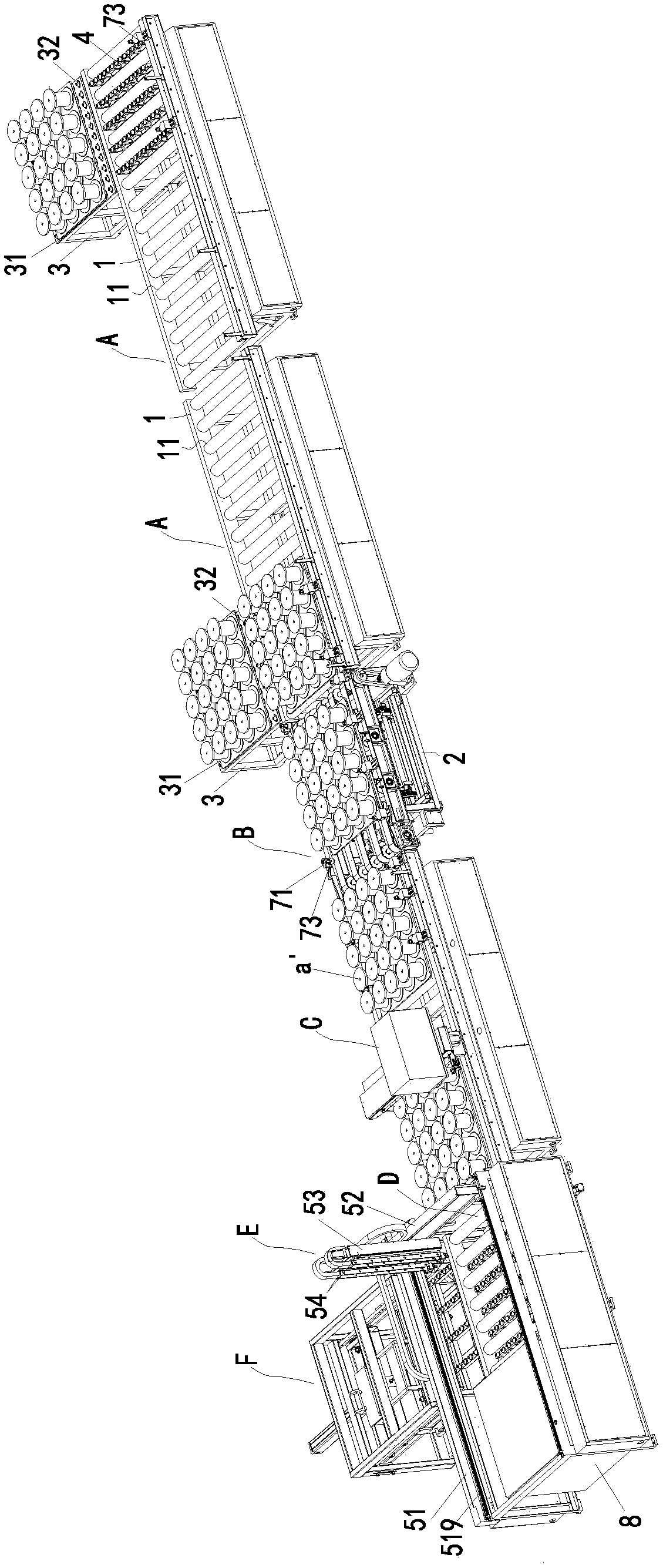
[0027] Such as Figure 1 to Figure 7 As shown, the embodiment of the present invention provides an automatic weighing and labeling device for steel wire coils, including a conveying device A arranged in accordance with the assembly line, a weighing device B for weighing the delivered products, and affixing the weighed products Labeling printer C for weight labeling, output device D for storing labeled products, product grabbing device E for grabbing and outputting products from the output device, and product removal of empty mold plates from the output device The mold plate is removed from the unit F. Labeling printer C is an outsourced product, purchased from Guangzhou Juhao Information Technology Co., Ltd., the model is: Bar code Printer IX300P, and the structure of this printer will not be described in detail in this invention.

[0028] The conveying device and the output device respectively include a conveying frame 1 and transmission shafts 11 arranged at intervals on th...


PUM


Abstract

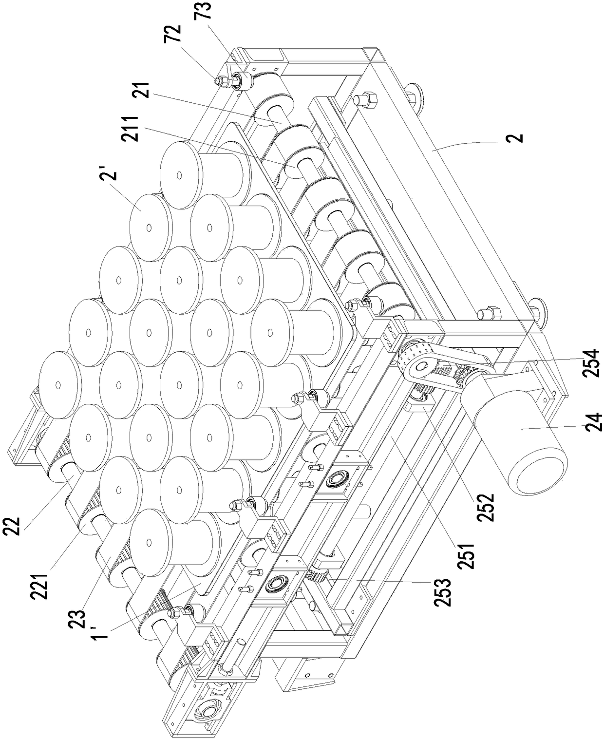
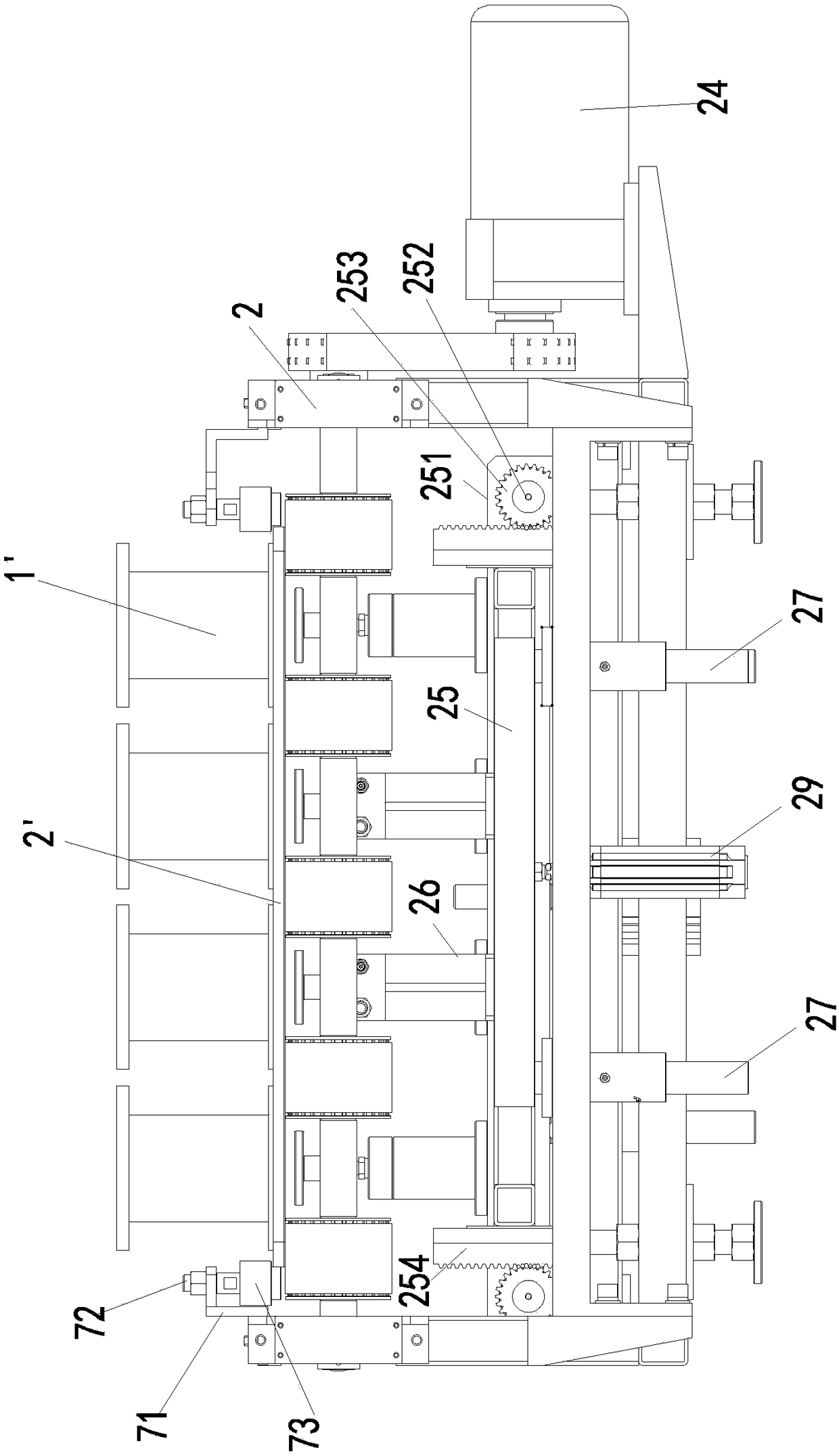
The invention discloses an automatic weighing and labeling device for a steel wire roll. The automatic weighing and labeling device for the steel wire roll comprises a conveying device, a weighing device, a label printing machine and an output device which are all sequentially arranged along an assembly line, wherein the weighing device is used for weighing the conveyed product, the label printingmachine pastes a weight label onto the weighed product, and the output device outputs and stores the labeled product. The weighing device comprises a weighing rack, main transmission rollers erectedon the two sides of the input end of a weighing rack and auxiliary transmission rollers erected on the two sides of the output end of the weighing rack. The main transmission rollers are provided withmain transmission wheels at intervals, the auxiliary transmission rollers are provided with auxiliary transmission wheels at intervals. The main transmission wheels and the auxiliary transmission wheels are correspondingly provided with and wound by belts or chains. The main transmission rollers are in transmission connection with a transmission device. A weighing lifting device is arranged belowthe weighing rack. The weighing lifting device comprises lifting bases which are arranged below the belts through lifting drive device in an ascending or descending manner, and the lifting bases areprovided with weighing sensors.

Description

technical field [0001] The invention relates to a weighing and labeling device, in particular to an automatic weighing and labeling device for steel wire coils. Background technique [0002] In industrial production, after the steel wire is formed and rolled, or after the formed wire is processed and rolled, in order to facilitate the packaging, sale, storage, or identification of the rolled steel wire, it is necessary to weigh the rolled steel wire And labeling, the existing technology uses manual weighing of the steel wire after winding, recording, and then manually affixing identification labels. This manual manual weighing and labeling method is labor-intensive, time-consuming and labor-intensive, and production efficiency is low. , and there is arbitrariness in manual weighing, large weighing errors and low precision. [0003] Although there are some automatic weighing machines on the market at present, their weighing efficiency is low, and it is impossible to automati...

Claims


Application Information

Patent Timeline
Patent Type & Authority Applications(China)
IPC IPC(8): B65C9/02B65C9/00B65G47/90B65G21/12
CPCB65C9/00B65C9/02B65G21/12B65G47/901
Inventor 吴明哲陈金在魏子能
Owner 东来不锈钢丝(厦门)有限公司
Learn More