A clamping and tightening device for an aluminum electrolytic cell
A jacking device and aluminum electrolytic cell technology, applied in the field of aluminum electrolysis, can solve problems such as increased workload, easily damaged anodes, high pressure, etc., and achieve the effects of increased contact area, low operating cost, and reduced voltage
- Summary
- Abstract
- Description
- Claims
- Application Information
AI Technical Summary
Problems solved by technology
Method used
Image
Examples
Embodiment 1
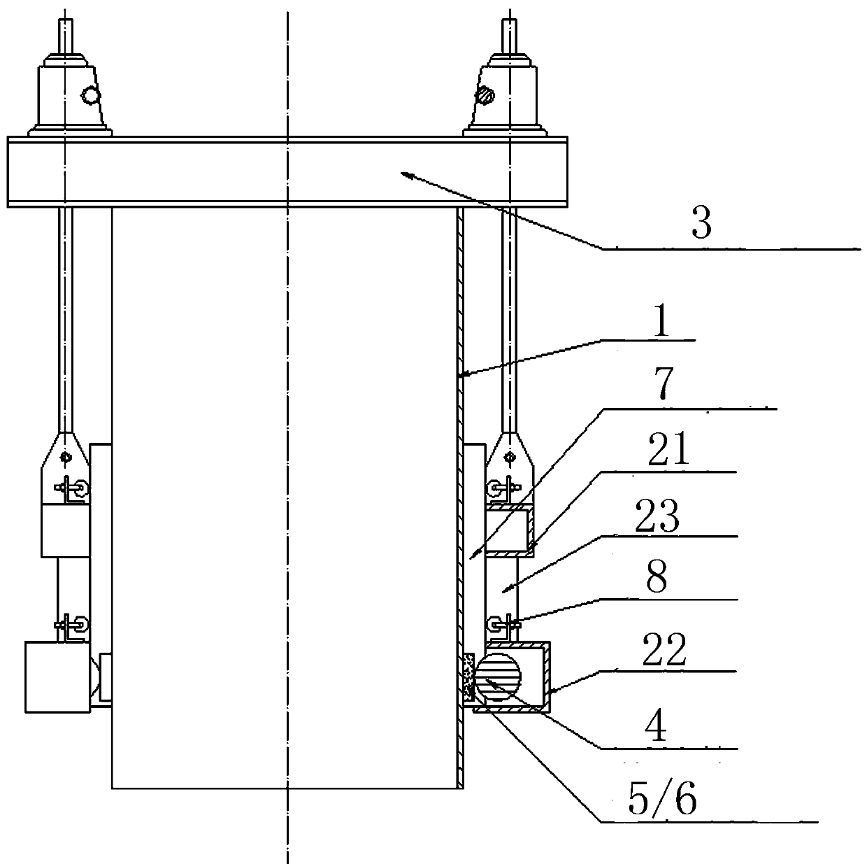
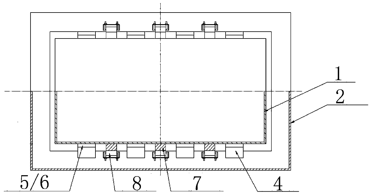
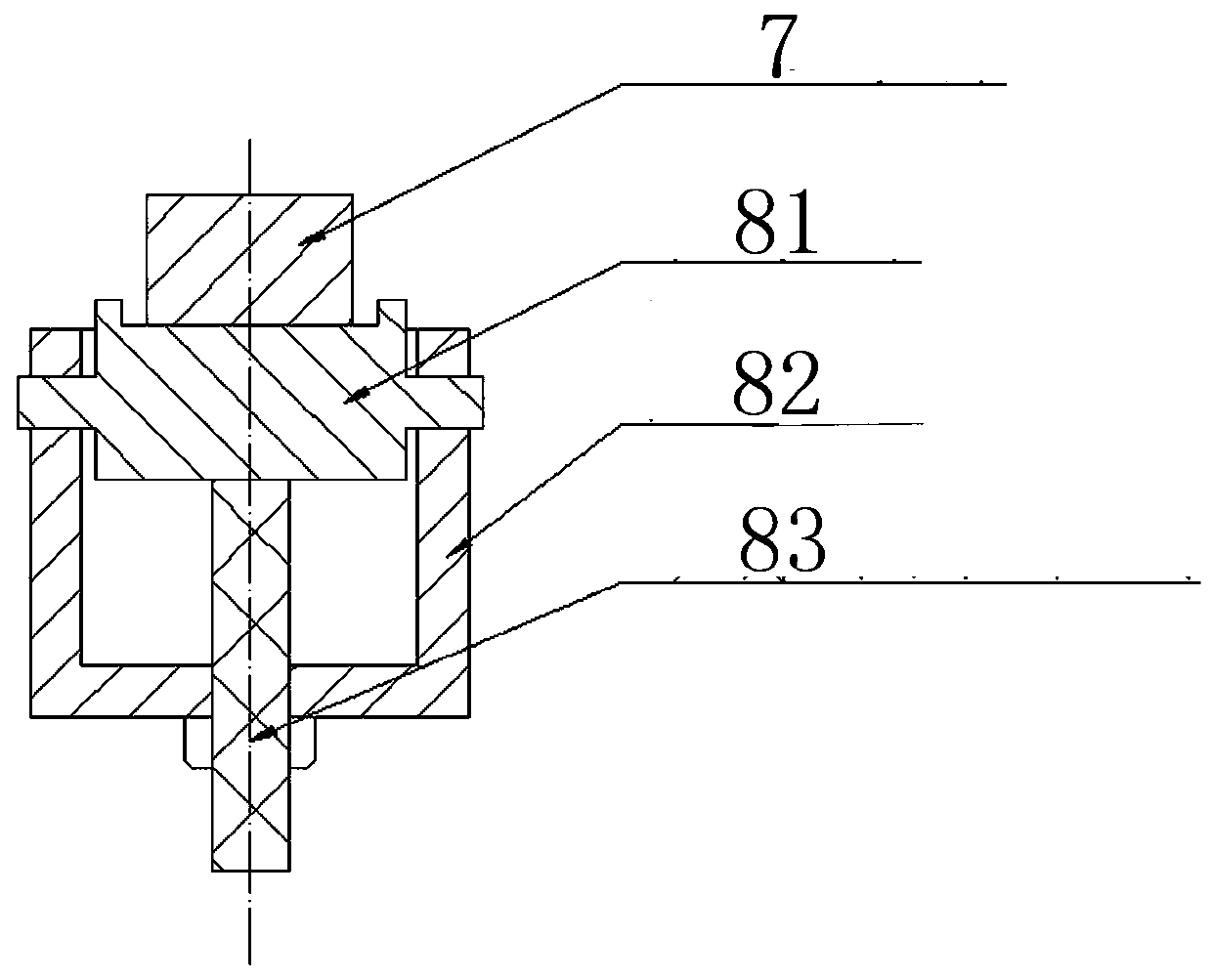
[0049] Such as figure 1 As shown, the clamping frame 2 is set around the aluminum frame 1 with several conductors, and then the clamping frame 2 is connected with the anode lifting mechanism 3. The clamping frame 2 is composed of two upper and lower rows (the upper row of clamping frames 21 And the lower row of clamping frames 22), the upper and lower rows of clamping frames are connected by a support 23. A number of clamps 4 are arranged in the lower row of clamping frames 22. The clamps 4 are located between the aluminum frame 1 and the clamping frame 2. A number of hanging plates 5 or flexible chains 6 are arranged around the clamps 4. A number of anode guide rods 7 are arranged between the aluminum frame 1 and the upper and lower rows of clamping frames, and a number of anchors 8 are arranged between the anode guide rod 7 and the clamping frame 2, and the anchors 8 are located in the upper and lower rows. Row the top of the clamping frame. Such as figure 2 As shown, the ...
Embodiment 2
[0064] Such as figure 1 As shown, the clamping frame 2 is first arranged around the aluminum frame 1 with several conductors, and then the clamping frame 2 and the anode lifting mechanism 3 are connected. The clamping frame 2 is a row. A number of clamps 4 are arranged in the clamping frame 2. The clamps 4 are located between the aluminum frame 1 and the clamping frame 2, and there are several hanging plates 5 around the clamps 4 Or flexible chain 6. A number of anode guide rods 7 are also arranged between the aluminum frame 1 and the clamping frame 2, and a number of anchors 8 are arranged between the anode guide rod 7 and the clamping frame 2. The anchors 8 are located in the clamping frame 2. Inside the groove and the top of the clamping frame. Such as figure 2 As shown, the anode lead 7 is located between two adjacent holders.
[0065] The number of jacks in contact with the anode guide rod 7 and the position and size of the pressure applied by the jack 8 on the anode gui...
Embodiment 3
[0077] Such as Picture 10 As shown, an anode lifting mechanism 3 is also provided around the clamping frame. The anode lifting mechanism 3 is located between the tank shell 10 and the upper structure 9 of the electrolytic cell. One end is connected to the tank shell and the other end is connected to the upper structure. The supporting frame is connected with the upper structure through the boom 11. When the anode lifting mechanism is activated, the upper structure of the electrolytic cell will be moved up and down, and the anode, hanging plate or flexible chain, clamping frame and clamp will be moved to the specified position simultaneously, and the clamping frame will be adjusted to the specified process Within the height range.
[0078] The anode lifting mechanism is a screw type lifting mechanism.
PUM
 Abstract
Description
Claims
Application Information
 - R&D
- Intellectual Property
- Life Sciences
- Materials
- Tech Scout
- Unparalleled Data Quality
- Higher Quality Content
- 60% Fewer Hallucinations
Browse by: Latest US Patents, China's latest patents, Technical Efficacy Thesaurus, Application Domain, Technology Topic, Popular Technical Reports.
© 2025 PatSnap. All rights reserved.Legal|Privacy policy|Modern Slavery Act Transparency Statement|Sitemap|About US| Contact US: help@patsnap.com


