Ultrasound transmission mode tomography method based on propagation path grid division

A transmission path and transmission path technology, applied in the direction of analyzing materials, processing detection response signals, instruments, etc., can solve problems such as differences in ray attenuation and attenuation forms, and achieve the effects of improving accuracy, improving image accuracy, and expanding the emission angle

Active Publication Date: 2020-07-31
TIANJIN UNIV
View PDF6 Cites 0 Cited by
  • Summary
  • Abstract
  • Description
  • Claims
  • Application Information

AI Technical Summary

Problems solved by technology

[0006] 1. The attenuation form of ultrasonic attenuation is different from that of ray attenuation

Method used


Image

  • Ultrasound transmission mode tomography method based on propagation path grid division
  • Ultrasound transmission mode tomography method based on propagation path grid division
  • Ultrasound transmission mode tomography method based on propagation path grid division

Examples


Embodiment Construction

[0025] The following detailed description of the steps of the present invention is intended to be described as an embodiment of the present invention, and is not the only form that can be manufactured or utilized. Other embodiments that can achieve the same function should also be included in the scope of the present invention.

[0026] Preferred embodiments of the present invention will be described in detail below in conjunction with the accompanying drawings.

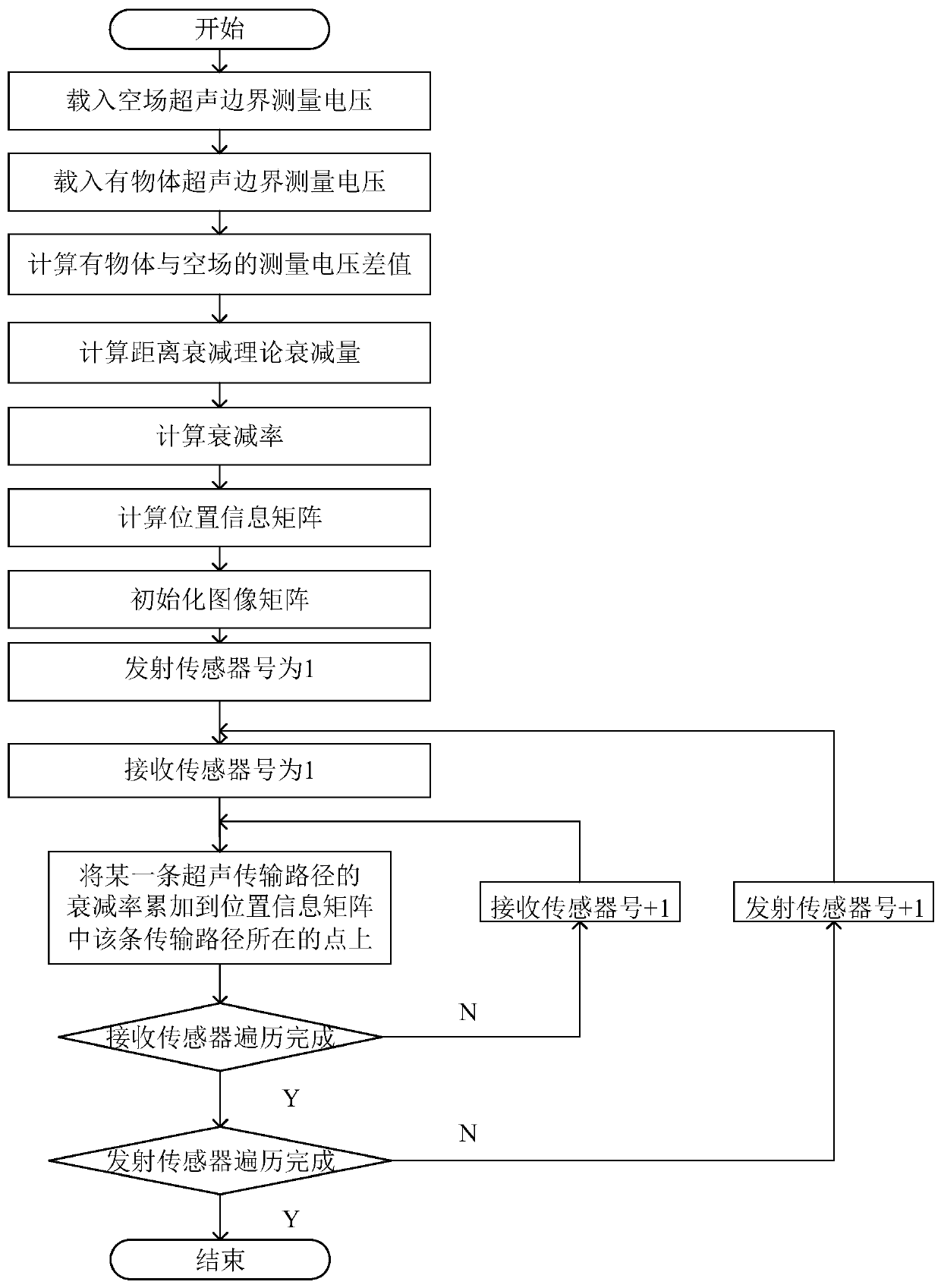
[0027] as attached figure 2 As shown, taking the 16-sensor ultrasound transmission mode tomography system as an example, the tomography process is as follows, and the imaging methods of other numbers of ultrasound probes are also applicable:

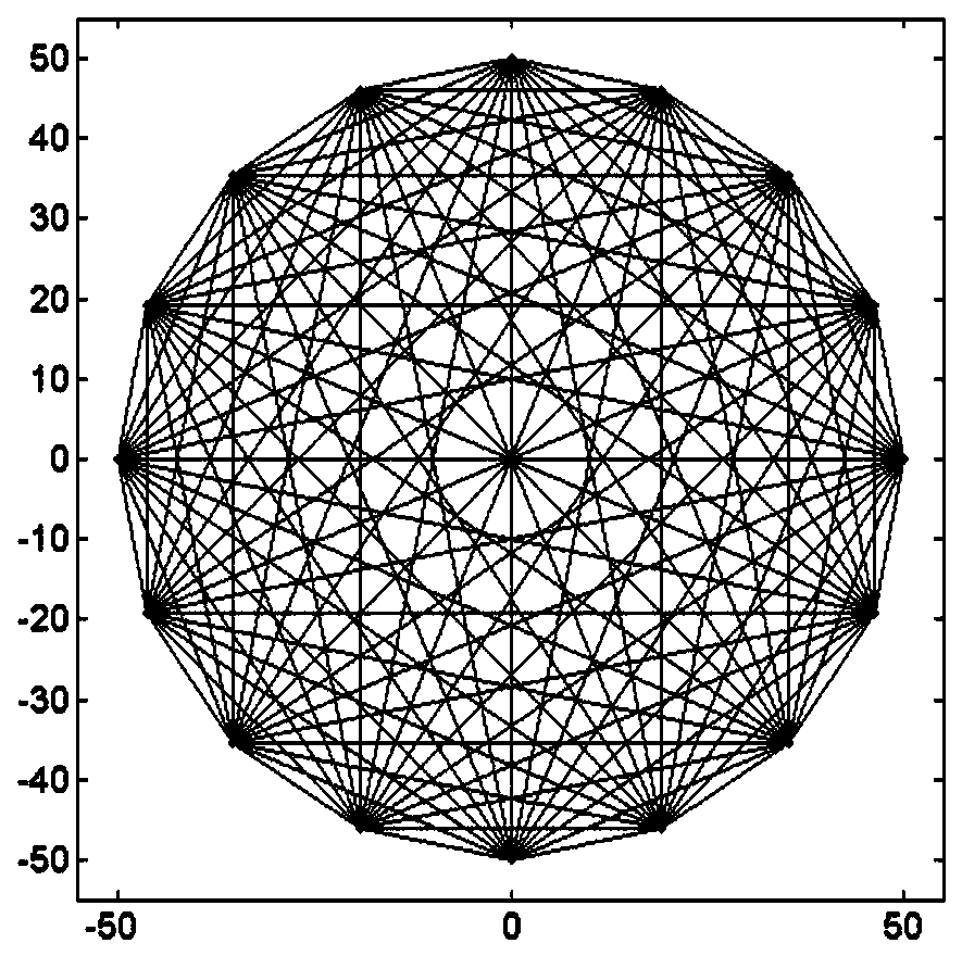
[0028] 1. Construct 16-sensor ultrasound transmission mode tomography grid division. Obtain grid matrix P and image matrix I

[0029] 2. Collect the ultrasonic boundary measurement voltage when there is no object in the measured object field and record it as V 0

[0030] 3...


PUM

PropertyMeasurementUnit
diameteraaaaaaaaaa

Abstract

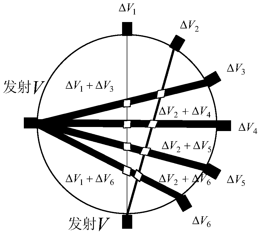
The invention relates to a propagation path mesh generation based ultrasonic transmission mode tomographic method, the central point of a tested area is taken as the origin of coordinates to constructa rectangular plane coordinate system, an image matrix I is constructed in the rectangular plane coordinate system, N ultrasonic sensors are distributed on the boundary of the tested area, a connecting line of any two ultrasonic sensors is an ultrasonic propagation path, the points of intersection of the ultrasonic propagation paths form an N*N grid matrix P. The traditional square or triangularmesh generation method is changed to irregular shape mesh generation based on the propagation characteristic of the ultrasonic wave to serve as the computing base. On the basis of the ultrasonic propagation path mesh generation method, the mesh generation based ultrasonic tomographic method is given.

Description

technical field [0001] The invention belongs to the field of ultrasonic tomography, and relates to a reconstruction method of ultrasonic transmission mode tomography, which is used in the image reconstruction process of ultrasonic transmission mode tomography. [0002] technical background [0003] Ultrasound transmission tomography (Ultrasound Tomography) is a kind of process tomography. The ultrasonic sensor installed at the boundary of the measured area is used to construct an ultrasonic field in the measured area. Since the ultrasonic wave propagates in the measured medium, it generates reflection and refraction. and other phenomena, the ultrasonic intensity received by the boundary of the measured field will attenuate, and the attenuation intensity is related to the change of acoustic impedance on the ultrasonic propagation path. Using this attenuation combined with a specific algorithm, the medium distribution image inside the measured area can be reversed. [0004] Th...

Claims


Application Information

Patent Timeline
Patent Type & Authority Patents(China)
IPC IPC(8): G01N29/44
CPCG01N29/44G01N2291/015G01N2291/018
Inventor 董峰张潍谭超
Owner TIANJIN UNIV
Why Eureka
Try Eureka