Switchgear thermal defect monitoring system, analysis method and comprehensive measuring control device thereof

A monitoring system and switchgear technology, which can be used in measuring devices, measuring electricity, measuring electrical variables, etc., and can solve problems such as incorrect monitoring results.

Inactive Publication Date: 2018-07-17
李宏仁
View PDF9 Cites 9 Cited by
  • Summary
  • Abstract
  • Description
  • Claims
  • Application Information

AI Technical Summary

Problems solved by technology

[0007] This (invention) provides a thermal defect monitoring device with a simple structure suitable for popularization, which can avoid the risk of temp

Method used


Image

  • Switchgear thermal defect monitoring system, analysis method and comprehensive measuring control device thereof
  • Switchgear thermal defect monitoring system, analysis method and comprehensive measuring control device thereof
  • Switchgear thermal defect monitoring system, analysis method and comprehensive measuring control device thereof

Examples


Embodiment 1

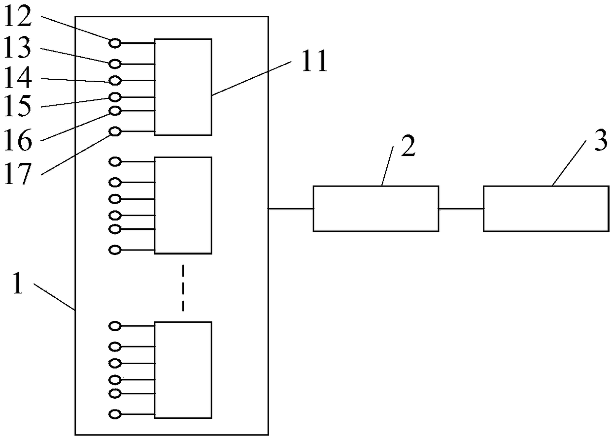
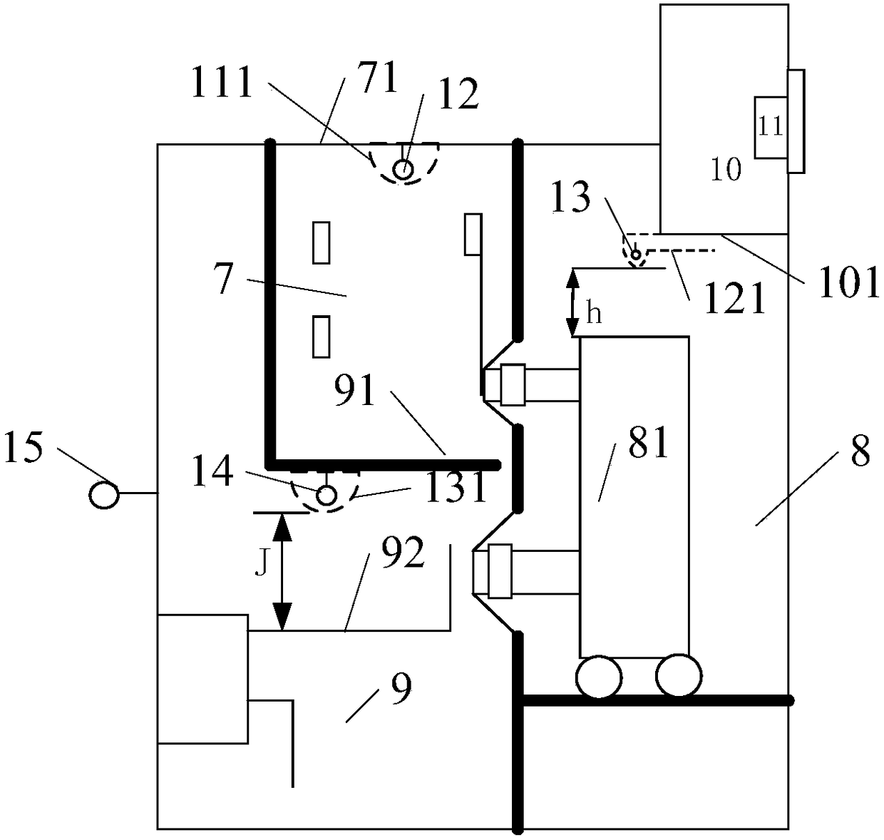
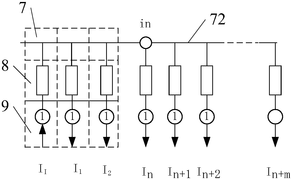
[0089] Example 1, please refer to figure 1 - Fig. 7 The thermal defect monitoring system of this embodiment includes: an information detection module 1, a communication module 2, and a data processing module 3; the information detection module 1 consists of a plurality of low-voltage sides respectively installed in each switch cabinet connected to the same group of busbars Composed of data acquisition units. Each low-voltage side data acquisition unit 11 includes 4 air temperature detection loops and 2 low-voltage side current detection loops to detect the ambient temperature, the air temperature of each compartment of the corresponding switchgear and the load current of these switchgears. Each data acquisition unit 11 is connected to the communication module 2 , and the communication module 2 is connected to the data processing module 3 . Ambient temperature sensor 15, compartment temperature sensors 12, 13, 14, current sensors 16, 17, these sensors are connected with the d...

Embodiment 2

[0106] Embodiment 2, the structure of this embodiment 2 and the embodiment 1 and the installation method in the switch cabinet are basically the same, the difference is that the aforementioned data acquisition unit 11 is replaced by the measurement and control device 4, and the measurement and control device 4 has the aforementioned thermal defect In addition to the temperature detection and current detection corresponding configurations of the low-voltage side data acquisition unit 11, there are also 1 gas detection circuit, 1 ultrasonic detection circuit, 1 photoelectric detection circuit and corresponding sensors 18, 19, 20; There are 2 circuit breaker closing and opening coil current detection circuits and current sensors 21, 22; and 2 auxiliary switch action signal detection circuits 23, 24; the measurement and control device 4 is also equipped with 2 circuits for controlling the entry and exit of the handcart of the circuit breaker The switch value output circuit 1DO, 2DO...


PUM

PropertyMeasurementUnit
Radius of curvatureaaaaaaaaaa

Abstract

The invention discloses a switchgear thermal defect monitoring system, an analysis method and a comprehensive measuring control device thereof. The system comprises an information detecting module, acommunication module and a data processing module, wherein the information detecting module comprises a plurality of data acquisition units at a low-voltage side. The data processing units are respectively mounted in switchgears which are connected with the same bus. The data acquisition unit comprises at least four air temperature detecting loops and at least one current detecting loop. A first air temperature detecting loop is used for an ambient temperature outside the switchgear. A second air temperature detecting loop, a third air temperature detecting loop and a fourth air temperature detecting loop are used for detecting the air temperature of each compartment of the corresponding switchgear. The current detecting loop is used for detecting the load current of the switchgear. Detected data are transmitted to the data processing module through the communication module. The data processing module determines whether a thermal defect of the switchgear exists based on the data transmitted from the communication module. The system can further used for monitoring multiple defects of the switchgear.

Description

technical field [0001] The invention relates to the field of on-line monitoring of switch cabinets, in particular to the discovery and monitoring of thermal defects that may cause accidents due to overheating of switch cabinets due to poor contact. Background technique [0002] High-voltage switchgear is commonly used equipment in power supply systems. Its structure usually includes: busbar room, circuit breaker room, cable room, secondary room and its internal components. Due to manufacturing quality and equipment aging, various defects and failures will appear inside the switchgear during operation, such as overheating, insulation aging, discharge, flashover, mechanical jamming, action failure and other defects. These defects often end up developing into serious switchgear accidents. Among the various defects of the switchgear, the overheating caused by the thermal defect of poor contact is the most troublesome problem in the power field. At present, there are very few a...

Claims


Application Information

Patent Timeline
IPC IPC(8): G01R31/02
CPCG01R31/50
Inventor 李宏仁陈建政肖红甄威魏文赋
Owner 李宏仁
Why Eureka
Try Eureka