Visual tracking method, visual tracking device, UAV(unmanned aerial vehicle) and terminal device

A technology of visual tracking and communication device, applied in the field of visual tracking, can solve the problems of inability to track, unmanned aerial vehicles cannot perform tracking, and high limitations, and achieve fast and accurate results.

Inactive Publication Date: 2018-07-17
SHANGHAI HANG SENG ELECTRONICS TECH CO LTD
View PDF5 Cites 6 Cited by
  • Summary
  • Abstract
  • Description
  • Claims
  • Application Information

AI Technical Summary

Problems solved by technology

Autonomous tracking based on GPS sensors usually requires the tracked object to carry a sensor with GPS positioning function or a similar positioning sensor. The internal processing chip of the tracking machine monitors the position of the tracked object in real time, and tracks the deviation between the current position of the machine and the target tracked object. , so as to guide the tracking machine to follow the tracked object. This tracking method has high limitations and cannot track the tracked object without a sensor with GPS positioning function or a similar positioning sensor.
Some vision-based autonomous tracking methods, such as the visual tracking method of drones, need to actively frame the target object and detect it. Only when the tracked object meets the detection conditions, the drone is driven to perform tracking. This method may It will cause the user to select the tracking object in the image multiple times. Due to human error, the tracked object still cannot meet the detection conditions, resulting in the UAV being unable to perform tracking.

Method used


Image

  • Visual tracking method, visual tracking device, UAV(unmanned aerial vehicle) and terminal device
  • Visual tracking method, visual tracking device, UAV(unmanned aerial vehicle) and terminal device
  • Visual tracking method, visual tracking device, UAV(unmanned aerial vehicle) and terminal device

Examples


Embodiment Construction

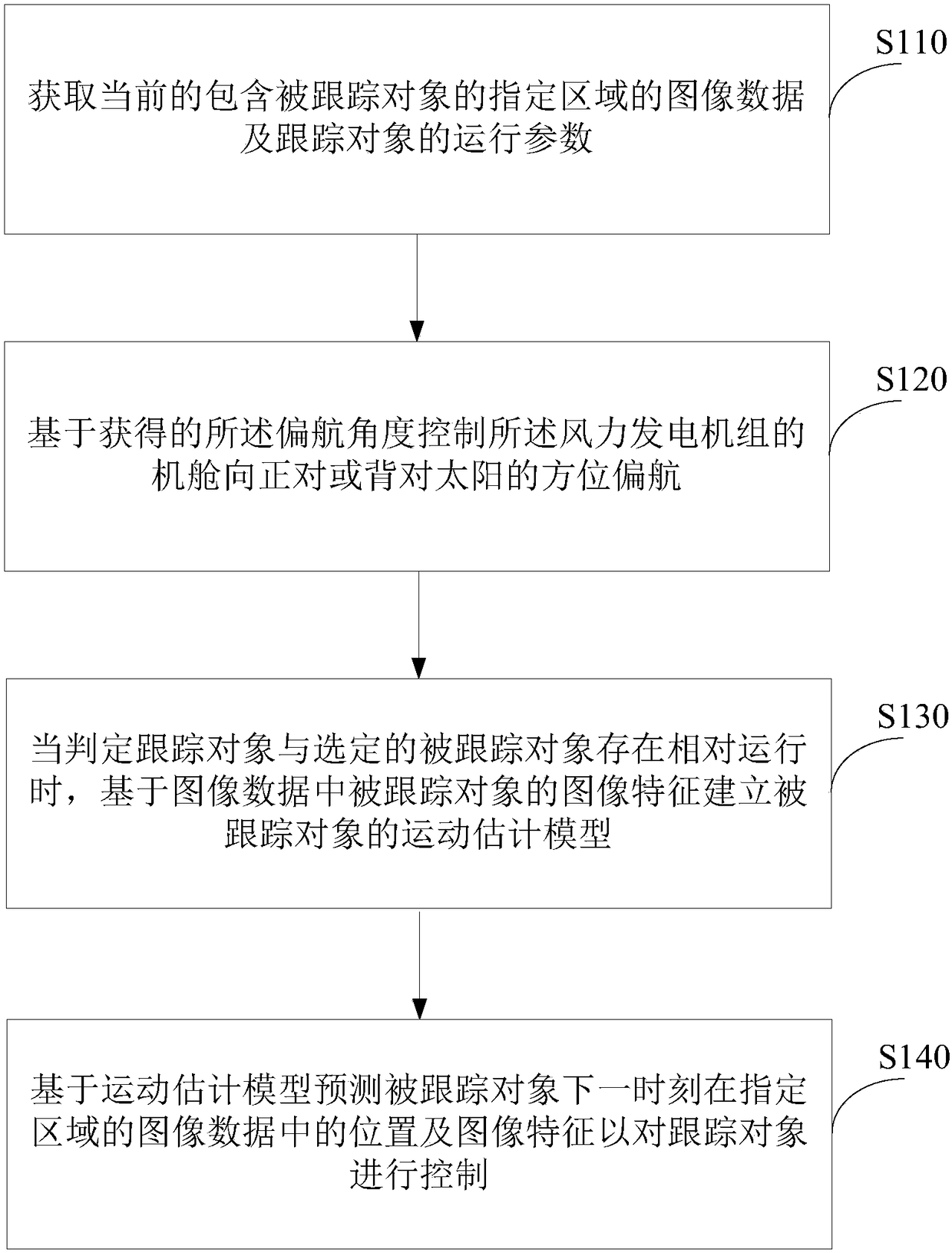
[0015] In order to make the purpose, technical solutions and advantages of the embodiments of the present invention clearer, the technical solutions in the embodiments of the present invention will be clearly and completely described below in conjunction with the drawings in the embodiments of the present invention. Obviously, the described embodiments It is a part of embodiments of the present invention, but not all embodiments. Based on the embodiments of the present invention, all other embodiments obtained by persons of ordinary skill in the art without creative efforts fall within the protection scope of the present invention.

[0016] Features and exemplary embodiments of various aspects of the invention will be described in detail below. In the following detailed description, numerous specific details are set forth in order to provide a thorough understanding of the present invention. It will be apparent, however, to one skilled in the art that the present invention ma...


PUM


Abstract

The invention discloses a visual tracking method, a visual tracking device, an UAV(unmanned aerial vehicle) and a terminal device. The method comprises the following steps: obtaining image data of a designated area comprising a tracked object at present and operating parameters of a tracking object; based on the obtained image data of the designated area comprising the tracked object at present, obtaining possible tracked objects in the designated area and generating a tracked object library to select the tracked object; when judging that the tracking object is in relative motion with the selected tracked object, establishing a motion estimation model of the tracked object based on image features of the tracked object in the image data; and based on the motion estimation model, predicatingthe position of the tracked object in the image data of the designated area at the next moment and image features to control the tracking object.

Description

technical field [0001] The invention belongs to the technical field of visual tracking, and in particular relates to a visual tracking method, a visual tracking device, a drone and a terminal device. Background technique [0002] Existing machine autonomous tracking usually includes GPS sensor-based autonomous tracking and vision-based autonomous tracking. Autonomous tracking based on GPS sensors usually requires the body of the tracked object to carry a sensor with GPS positioning function or a similar positioning sensor. The internal processing chip of the tracking machine monitors the position of the tracked object in real time, and tracks the deviation between the current position of the machine and the position of the target tracked object. , so as to guide the tracking machine to follow the tracked object. This tracking method has high limitations and cannot track the tracked object without a sensor with GPS positioning function or a similar positioning sensor. Some v...

Claims


Application Information

Patent Timeline
Patent Type & Authority Applications(China)
IPC IPC(8): G06T7/246
CPCG06T2207/10016B64U2101/30G05D1/0094G06T2207/10032G06T2207/30244G06T7/246G06T7/70B64C39/024G06T7/20B64U2201/10
Inventor 田瑜江文彦
Owner SHANGHAI HANG SENG ELECTRONICS TECH CO LTD
Why Eureka
Try Eureka