Coolant pump for an internal combustion engine

A technology for coolant pumps and internal combustion engines, applied in engine cooling, liquid cooling, pumps, etc., can solve the problems of impossible layout and installation, increased location requirements, increased installation costs, etc., and achieves simple installation, precise axial movement, and high reliability effect

Active Publication Date: 2018-07-17
PIERBURG GMBH & CO KG NEUSS
View PDF5 Cites 0 Cited by
  • Summary
  • Abstract
  • Description
  • Claims
  • Application Information

AI Technical Summary

Problems solved by technology

Furthermore, there are increased installation costs and especially increased space requirements for the schematically explained flow guidance and due to the chosen arrangement and housing parts, so that such pumps cannot be arranged and installed in the corresponding corresponding parts of the cylinder crankcase. design

Method used


Image

  • Coolant pump for an internal combustion engine
  • Coolant pump for an internal combustion engine

Examples


Embodiment Construction

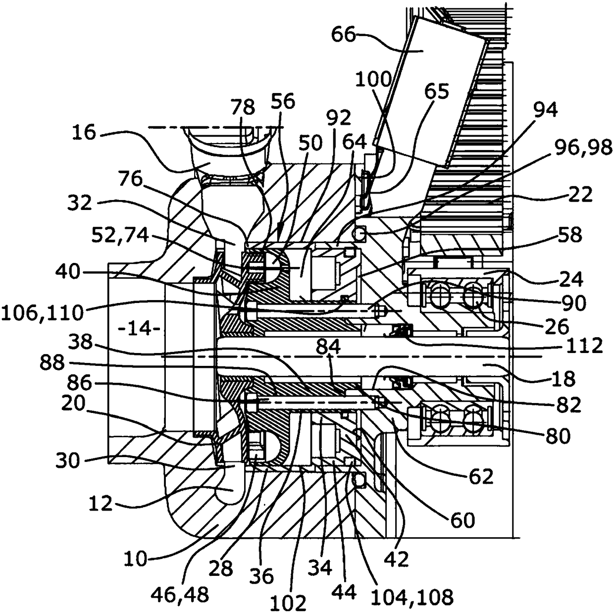
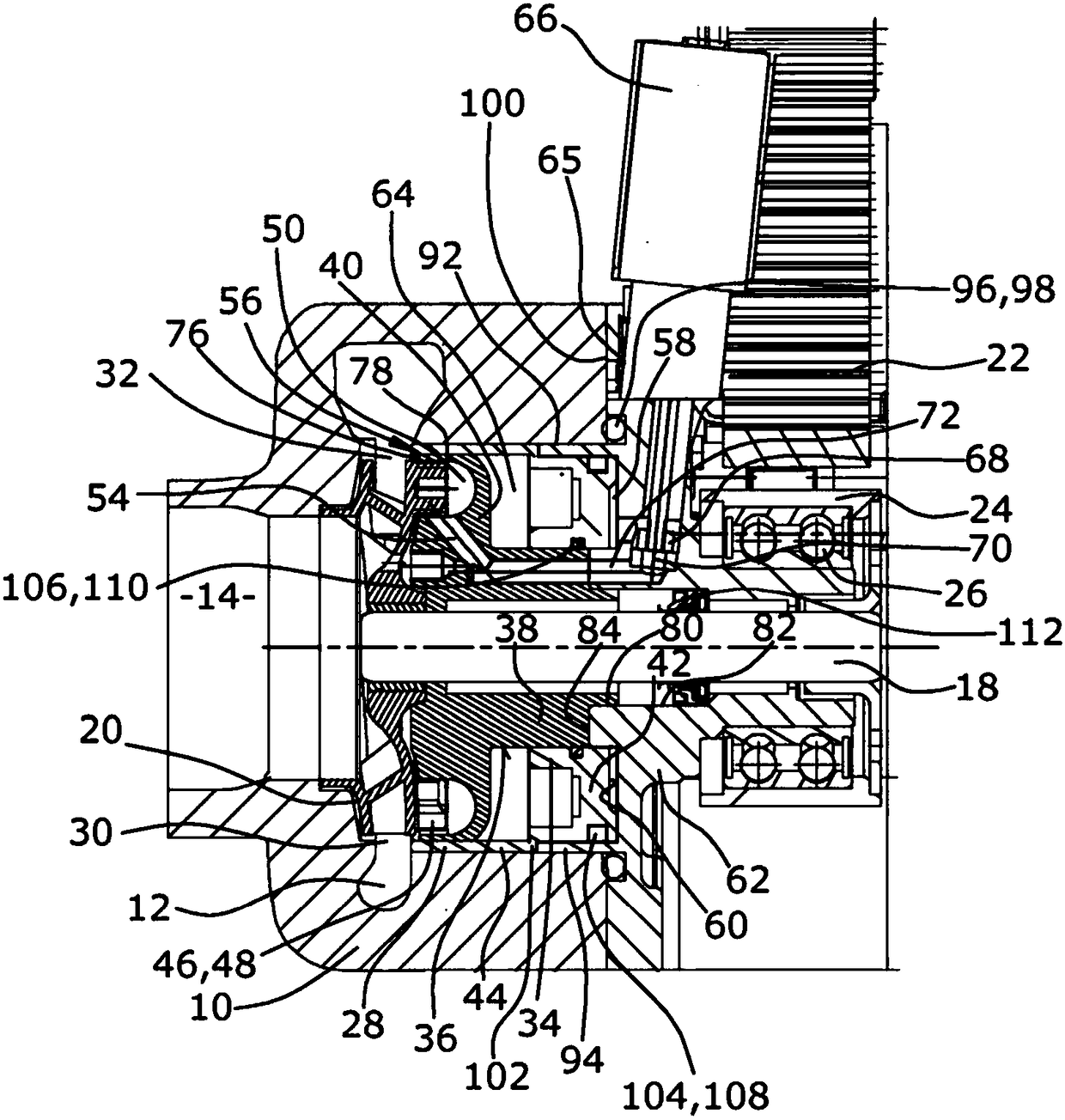
[0025] The coolant pump according to the invention comprises an outer housing 10 in which a helical delivery channel 12 is formed, in which cooling is sucked in via an axial pump inlet 14 also formed in the outer housing 10 The coolant is delivered via the delivery channel 12 into a tangential pump outlet 16 formed in the outer housing 10 and into the cooling circuit of the internal combustion engine. Furthermore, the housing 10 can be formed in particular by a cylinder crankcase which has a recess for receiving the remaining coolant pump.

[0026] For this, a coolant pump impeller 20 is fastened radially in the delivery channel 12 on the drive shaft 18 , said coolant pump impeller 20 is formed as a radial pump wheel, the rotation of which achieves the cooling of the coolant. Delivery in the delivery channel 12.

[0027] The drive of the turbine pump impeller 20 takes place via a drive belt 22 which drives a pulley 24 which is fastened on the axial end of the drive shaft 18 o...


PUM


Abstract

The invention relates to a coolant pump for an internal combustion engine. The coolant pump is equipped with a drive shaft (18), having a coolant pump impeller (20) which is arranged at least rotationally conjointly on the drive shaft (18) and by means of which coolant can be delivered into a delivery duct (12) surrounding the coolant pump impeller (20), having an adjustable regulating slide (28)by means of which a throughflow cross section of a ring-shaped gap (30) between an outlet (32) of the coolant impeller (20) and the delivery duct (12) can be regulated, having a side channel pump (56)with a side channel pump impeller (46) which is arranged at least rotationally conjointly on the drive shaft (18), having a side channel (50) of the side channel pump (56), in which side channel a pressure can be generated as a result of rotation of the side channel pump impeller (46), having a pressure duct (72) via which an outlet (54) of the side channel (50) is fluidically connectable to a first pressure chamber (58) of the regulating slide (28), and having a valve (66) by means of which a throughflow cross section (70) of the pressure duct (72) can be closed and opened up, are known. Toshorten the structural space thereof in particular axially, it is proposed that the coolant pump impeller (20) is formed in one piece with the side channel pump impeller (46), and the side channel (50) is formed in a first housing part (40) on which the regulating slide (28) is slidingly guided.

Description

technical field [0001] The invention relates to a coolant pump for an internal combustion engine with a drive shaft and a coolant pump impeller arranged at least in a rotationally fixed manner on the drive shaft and passing through the coolant pump impeller The coolant can be delivered into the delivery channel around the coolant pump impeller; the adjustable control slider can regulate the flow width of the annular gap between the outlet of the coolant pump impeller and the surrounding delivery channel. Cross section; side channel pump with side channel pump impeller, said side channel pump impeller is arranged at least torsionally fixedly on the drive shaft; side channel of side channel pump, in said side channel by rotation of side channel pump impeller Pressure generation; a pressure channel, via which the outlet of the side channel can be fluidically connected to the first pressure chamber of the control slide; and a valve, via which the flow cross section of the pressure...

Claims


Application Information

Patent Timeline
Patent Type & Authority Applications(China)
IPC IPC(8): F04D5/00F04D13/12F04D15/00
CPCF04D5/002F04D15/0038F05D2270/64F01P5/10F01P2003/001F01P2005/105F04D13/12
Inventor 斯特凡·齐尔伯格安德雷斯·伯格米夏埃尔-托马斯·本拉斯特凡·洛特冈米夏埃尔·贝克尔
Owner PIERBURG GMBH & CO KG NEUSS
Why Eureka
Try Eureka