A multi-angle processing jig for bone plate

A multi-angle, bone plate technology, applied in the direction of manufacturing tools, metal processing equipment, metal processing machinery parts, etc., can solve the problems of workpieces that cannot be processed with large-angle curved surfaces, low processing efficiency, and high fixture manufacturing costs

Active Publication Date: 2020-02-14
安徽威宇医疗器械科技有限公司
View PDF5 Cites 0 Cited by
  • Summary
  • Abstract
  • Description
  • Claims
  • Application Information

AI Technical Summary

Problems solved by technology

[0002] The processing device of the previous three-axis machining center can only process workpieces with a single angle. When using machining, it cannot process workpieces with large-angle curved surfaces. The limitations are large. For example, the main processes of straight bone plate processing include hole processing and end surface processing. , In actual processing, multiple fixtures are usually required and clamped multiple times to complete the processing of the bone plate. The manufacturing cost of the fixture is high and the processing efficiency is low. Now there is a need for a fixture that is easy to operate and convenient to process all angles of the bone plate

Method used


Image

  • A multi-angle processing jig for bone plate
  • A multi-angle processing jig for bone plate
  • A multi-angle processing jig for bone plate

Examples


Embodiment Construction

[0016] Preferred embodiments of the present invention will be described in detail below in conjunction with the accompanying drawings.

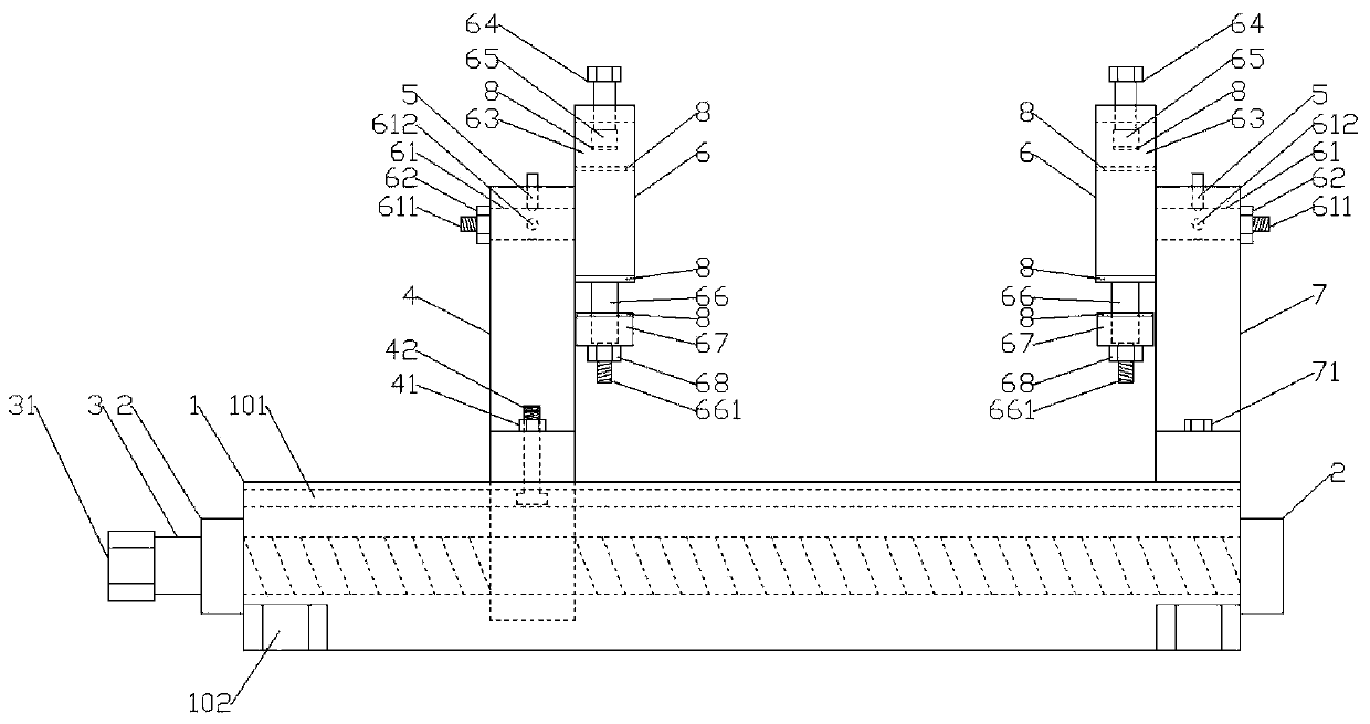
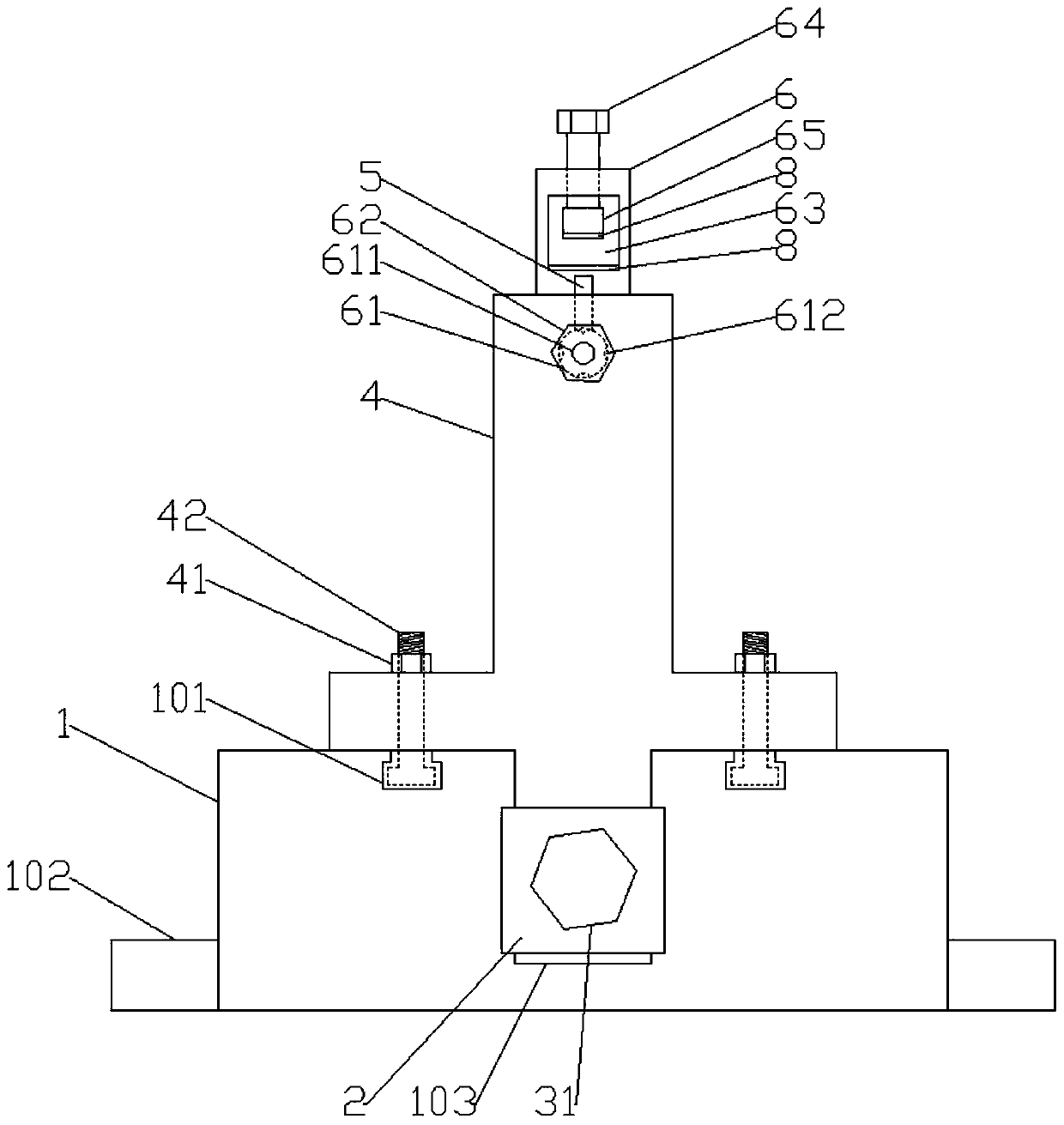
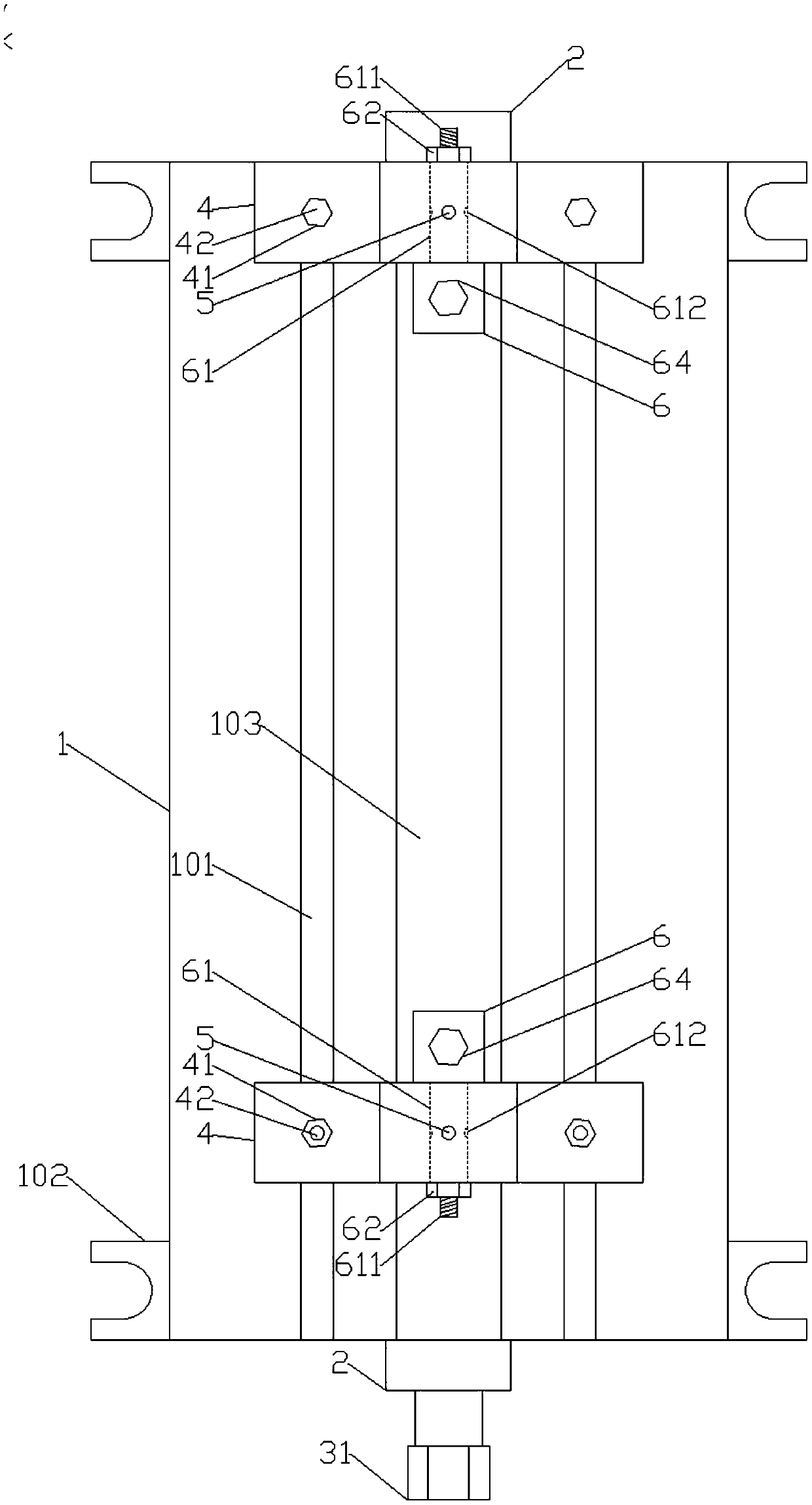
[0017] Figure 1-5 A specific embodiment of the present invention is shown: a multi-angle processing jig for bone plates, including a base 1, a chute 103 is provided in the middle of the base 1, T-shaped grooves 101 are provided on both sides of the chute 103, and the Both ends of the base 1 are provided with a screw seat 2, the screw seat 2 is provided with a screw 3, one end of the base 1 is provided with a T-shaped seat 7, and the two ends of the T-shaped seat 7 are respectively fixed with bolts 71 Fixed on the base 1, the other end of the base 1 is provided with a cross-shaped sliding seat 4 and the lower end is located in the chute 103, the sliding seat 4 is threadedly connected with the screw rod 3, and the two ends of the sliding seat 4 A locking bolt 42 is provided, and the head of the locking bolt 42 is located in the T-shaped groov...


PUM


Abstract

The invention discloses a multi-angle machining clamp for a bone fracture plate. The multi-angle machining clamp comprises a base. A sliding groove is formed in the middle portion of the base, and T-shaped grooves are formed in the two sides of the sliding groove. Lead screw bases are arranged at the two ends of the base and internally provided with lead screws. A T-shaped base is arranged at oneend of the base, and a sliding base is arranged at the other end of the base. Locking bolts are arranged at the two ends of the sliding base. Each locking bolt is provided with a first nut. The upperend of the sliding base and the upper end of the T-shaped base are in cup joint with first fixing rods. Four positioning holes are evenly distributed in the middle portion of each first fixing rod along the circumference. The sliding base and the T-shaped base are provided with fixing pins. A first screw is arranged at one end of each first fixing rod and provided with a second nut, a stand columnis arranged at the other end of each first fixing rod, a rectangular hole is formed in the upper end of each stand column, a rotation rod is arranged at the upper end of each rectangular hole, and apressing block is arranged at the bottom of each rotation rod. A second fixing rod is arranged at the lower end of each stand column, a second screw is arranged at the front end of each second fixingrod, each second fixing rod is in cup joint with a limiting block, and each second screw is provided with a third nut. The clamp manufacturing cost is relatively low, and the clamp has the beneficialeffects of being high in positioning precision, resistant to abrasion, convenient to use and the like.

Description

technical field [0001] The invention relates to the field of medical device processing, in particular to a multi-angle processing jig for bone plates. Background technique [0002] The processing device of the previous three-axis machining center can only process workpieces with a single angle. When using machining, it cannot process workpieces with large-angle curved surfaces. The limitations are large. For example, the main processes of straight bone plate processing include hole processing and end surface processing. , In actual processing, multiple fixtures are usually required to complete the processing of the bone plate, and the manufacturing cost of the fixture is high, and the processing efficiency is low. Now there is a need for a fixture that is easy to operate and convenient to process all angles of the bone plate. Contents of the invention [0003] The technical problem to be solved by the present invention is to provide a multi-angle processing jig for bone pl...

Claims


Application Information

Patent Timeline
Patent Type & Authority Patents(China)
IPC IPC(8): B23Q3/04B23Q3/06
CPCB23Q3/04B23Q3/06
Inventor 金鑫
Owner 安徽威宇医疗器械科技有限公司
Why Eureka
Try Eureka