Drill bit positioning device of woodworking drilling equipment

A technology for drilling equipment and positioning devices, which is applied in the field of drilling machines, can solve the problems of poor equipment positioning and easy loosening of drill bits, and achieve the effects of reducing drilling errors, avoiding drill pipe deviation, and accelerating sliding speed

Active Publication Date: 2022-08-05
新沂市凯宁工具有限公司
View PDF9 Cites 0 Cited by
  • Summary
  • Abstract
  • Description
  • Claims
  • Application Information

AI Technical Summary

Problems solved by technology

[0004] Aiming at the deficiencies of the prior art, the present invention provides a drill bit positioning device for woodworking drilling equipment, which solves the problem that the drill bit of the traditional drilling machine is easy to loosen and the positioning effect of the equipment is poor

Method used


Image

  • Drill bit positioning device of woodworking drilling equipment
  • Drill bit positioning device of woodworking drilling equipment
  • Drill bit positioning device of woodworking drilling equipment

Examples


Embodiment 1

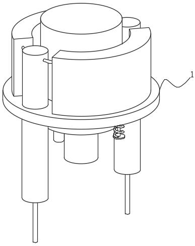
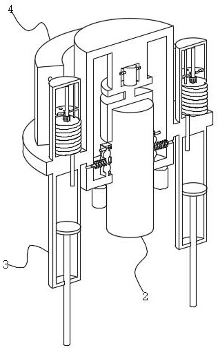
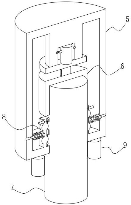
[0033] see Figure 1-Figure 8 , the present invention provides a technical solution: a drill bit positioning device for woodworking drilling equipment, comprising a connecting plate 1, the inner surface of the connecting plate 1 is fixedly connected with a driving device 2, and the left and right sides of the driving device 2 are provided with vertical buffers Device 3, the upper surface of the connecting plate 1 is fixedly connected with a pressure relief device 4, the driving device 2 includes a turning block 5, the inner surface of the turning block 5 is fixedly connected with a magnetic suction device 6, and the bottom of the magnetic suction device 6 is provided with a drill pipe 7 The outer surface of the drill pipe 7 is movably connected with a clamping device 8 , the bottom of the clamping device 8 is provided with a laser transmitter 9 , and the upper surface of the laser transmitter 9 is fixedly connected with the lower surface of the rotating block 5 .

[0034] The ...

Embodiment 2

[0040] see Figure 1-Figure 8 , the present invention provides a kind of technical scheme:

[0041] According to a drill bit positioning device of a woodworking drilling equipment according to claim 1, the vertical buffer device 3 comprises a pressing rod 25, the outer surface of the pressing rod 25 is slidably connected to the sealing pipe 26, and the top of the sealing pipe 26 is fixedly connected with a connecting pipe 27, A metering device 28 is fixedly connected to the top end of the connecting pipe 27 .

[0042] The metering device 28 includes a fixed cylinder 30, the inner surface of the fixed cylinder 30 is rotatably connected with a rotating shaft 31, the outer surface of the rotating shaft 31 is fixedly connected with a clamping block 32, the bottom of the clamping block 32 is provided with a screw 33, and the top of the screw 33 is provided with a movable plate 34, the inner surface of the movable plate 34 is slidably connected with a guide rod 35, the upper surfac...


PUM


Abstract

The invention discloses a drill bit positioning device of woodworking drilling equipment, the drill bit positioning device comprises a connecting plate, the inner surface of the connecting plate is fixedly connected with a driving device, the left side and the right side of the driving device are provided with vertical buffer devices, and the upper surface of the connecting plate is fixedly connected with a pressure relief device. According to the drill bit positioning device of the woodworking drilling equipment, by arranging the driving device, when the equipment is used, the driving device is driven by an external motor to rotate, a rotating block drives a connecting plate to rotate, a drill bit is welded to the bottom end of a drill rod, the drill rod is inserted into the rotating block, a magnetic attraction device attracts and fixes the drill rod, and a clamping device prevents the drill rod from loosening; in the drilling process of the equipment, the laser transmitter continuously transmits and receives laser, so that the vertical drilling depth of the drill bit is judged, the drilling error is reduced, and the problems that a traditional drill bit is poor in positioning precision and large in error are solved.

Description

technical field [0001] The invention relates to the technical field of drilling machines, in particular to a drill bit positioning device of woodworking drilling equipment. Background technique [0002] Drilling machine refers to a machine tool that mainly uses a drill to process holes on a workpiece. Usually, the rotation of the drill is the main movement, and the axial movement of the drill is the feed movement. The drilling machine has a simple structure and relatively low machining accuracy. It can drill through holes and blind holes, replace special tools, and can ream, countersink, ream or tap. [0003] When a traditional drilling rig drills a sheet, due to the need to drill holes of different specifications on a single sheet, it is necessary to replace the drill frequently, multiple replacements, gaps are easily formed between the drill and the drill, the drill is easy to fall off, and it is easy to tilt when drilling. The positioning during drilling cannot be comple...

Claims


Application Information

Patent Timeline
Patent Type & Authority Applications(China)
IPC IPC(8): B27C3/02B27G21/00
CPCB27C3/02B27G21/00
Inventor 杨招英
Owner 新沂市凯宁工具有限公司
Why Eureka
Try Eureka