a power head

A power head and driven wheel technology, applied in the field of machinery, can solve the problems of poor stability of the power head, and achieve the effects of good concentricity, improved stability and small rotation error.

Active Publication Date: 2022-04-12
ZHEJIANG SHUANGZHENG MACHINE TOOL CO LTD
View PDF16 Cites 0 Cited by
  • Summary
  • Abstract
  • Description
  • Claims
  • Application Information

AI Technical Summary

Problems solved by technology

[0005] The purpose of the present invention is to solve the problem of poor stability of the existing power head in the state of starting and stopping in order to solve the above-mentioned problems in the existing technology.

Method used


Image

  • a power head
  • a power head
  • a power head

Examples


Embodiment Construction

[0035] The following are specific embodiments of the present invention and in conjunction with the accompanying drawings, the technical solutions of the present invention are further described, but the present invention is not limited to these embodiments.

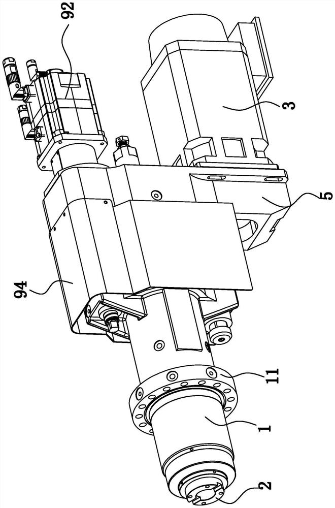
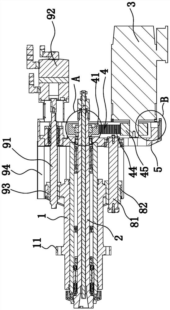
[0036] like figure 1 , figure 2 As shown, a power head, specifically a servo power head in this embodiment, includes a main body 1 and a main shaft 2 pierced in the main body 1, and the main body 1 is provided with a connecting flange 11 for connecting a machine tool. The present invention The power head is attached to the machine tool through the flange surface of the connection flange 11 arranged on the body 1 and plays a connection role. The body 1 is also connected with the motor box 5 axially connected with the main shaft 2, the motor box 5 is fixedly connected with the guide rod 81 parallel to the axial direction of the main shaft 2, the body 1 is fixedly connected with the guide sleeve 82, and the guide rod 81 pas...


PUM


Abstract

The invention provides a power head, which belongs to the technical field of machinery. It solves the problem of poor stability of the existing power head when it starts and stops. The power head of the improved structure includes a main body and a main shaft passing through the main body, the main body is provided with a connecting flange for connecting to a machine tool, the power head also includes a rotation driving source for driving the main shaft to rotate, and a main shaft for driving the main shaft to rotate. A synchronous pulley transmission assembly connecting a rotary drive source and a main shaft, the synchronous pulley transmission assembly includes a driven wheel sleeved outside the main shaft, characterized in that the rotary drive source and the main shaft are axially fixed, and the driven wheel A ring-shaped expansion sleeve is arranged between the expansion sleeve and the main shaft. The outer peripheral wall of the expansion sleeve abuts against the driven wheel and the inner peripheral wall of the expansion sleeve abuts against the main shaft. The driven wheel is expanded and positioned on the main shaft through the expansion sleeve. . The power head of the improved structure has good stability in the start-stop state.

Description

technical field [0001] The invention belongs to the technical field of machinery, and relates to a machined part, in particular to a power head. Background technique [0002] The power head is a power component that can realize main movement and feed movement, and has automatic workpiece circulation. It is a relatively simple variable speed transmission mechanism with various forms. The basic principle is that the motor drives a gear transmission mechanism, which can realize functions such as boring, milling, and drilling. Some have guide rails and can move linearly in a small range. The power head mainly realizes different processing through the rotation and feed of the main shaft. The existing middle power head is divided into horizontal type and vertical type according to the way it cooperates with the installation surface of the machine tool. The body of the vertical power head is provided with a connecting flange, which is connected against the machine tool through the...

Claims


Application Information

Patent Timeline
Patent Type & Authority Patents(China)
IPC IPC(8): B23B19/00B23B19/02B23Q5/10
CPCB23Q1/70B23Q5/10
Inventor 陈云法
Owner ZHEJIANG SHUANGZHENG MACHINE TOOL CO LTD
Why Eureka
Try Eureka