Worm gear machine tool

A technology of worm gear and parent machine, which is applied in the direction of worm gear, gear teeth, worm, etc., can solve the problems of difficult traceability of machining errors, low efficiency, and large heat generation at the cutting interface of hobbing processing, etc., to achieve improved rigidity, good versatility, and improved transmission The effect of precision

Pending Publication Date: 2021-06-18
CHONGQING UNIV
View PDF8 Cites 0 Cited by
  • Summary
  • Abstract
  • Description
  • Claims
  • Application Information

AI Technical Summary

Problems solved by technology

[0003] The enveloping motion of high-precision worm gear machining is complicated, and the heat generated by the cutting interface of rolling shaving machining is large, and the thermal error accounts for more than 70%; and the multi-axis linkage generating machining error is difficult to trace the source, and the trial and error adjustment method is usually used for comprehensive error compensation, that is, : By comparing the trial-cut tooth surface with the designed tooth surface, the measured tooth shape and tooth direction error are obtained. Based on this, the worm gear tool is reversely modified and the machine tool path is reversely set before processing, and the tooth required by the design is obtained through multiple iterative processing. Surface accuracy, this comprehensive error control method is difficult to improve machining and modification accuracy, and the efficiency is extremely low
At present, due to the lack of high-precision worm gear shape controllable processing technology and tooling, it is difficult to achieve high-precision and efficient machining of worm gears, and the service performance of worm gears cannot be guaranteed.

Method used


Image

  • Worm gear machine tool
  • Worm gear machine tool
  • Worm gear machine tool

Examples


Embodiment Construction

[0069] The present invention will be further described below in conjunction with the accompanying drawings and specific embodiments, so that those skilled in the art can better understand the present invention and implement it, but the examples given are not intended to limit the present invention.

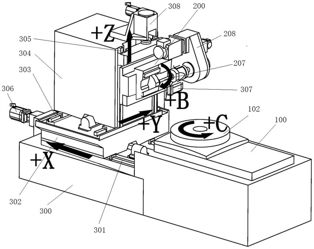
[0070] Such as figure 1 Shown is a schematic structural view of an embodiment of the worm gear machine of the present invention. The worm gear machine of this embodiment includes a workbench 100 for clamping a worm gear workpiece, a tool rest 200 for clamping a tool, and a tool rest adjustment system for adjusting the position of the tool rest 2 relative to the workbench 1 . The tool post adjustment system of this embodiment includes a base 300, on which an X-guiding rail 301 and a pedestal 302 slidingly fitted with the X-guiding rail 301 are provided, and on the pedestal 302, a Y-guiding rail 303 perpendicular to the X-guiding rail 301 and a Y-guiding rail 303 and The tool rest ...


PUM


Abstract

The invention discloses a worm gear machine tool. The worm gear machine tool comprises a workbench used for clamping a worm gear workpiece, a tool rest used for clamping a tool and a tool rest adjusting system used for adjusting the position of the tool rest relative to the workbench; the tool rest comprises a large bracket, a first sliding rail is arranged on the large bracket, a sliding seat in sliding fit with the first sliding rail is arranged on the first sliding rail, a second sliding rail is arranged on the sliding seat, a small bracket in sliding fit with the second sliding rail is arranged on the second sliding rail, and the first sliding rail is parallel to the second sliding rail; a tool rest main shaft is arranged between the large bracket and the sliding seat, a knife bar synchronously rotating with the tool rest main shaft is arranged between one end, facing the small bracket, of the tool rest main shaft and the small bracket, and a gear box used for driving the tool rest main shaft to rotate is arranged in the large bracket; and a first hydrostatic bearing mechanism is arranged between the sliding seat and the tool rest main shaft, and a second hydrostatic bearing mechanism is arranged between the tool bar and the small bracket.

Description

technical field [0001] The invention belongs to the technical field of mechanical processing equipment, in particular to a worm gear parent machine. Background technique [0002] Mechanical drive and transmission are the foundation of the equipment manufacturing industry. Among them, the worm gear pair is the key basic component for transmitting motion and power, and also the key core component for ensuring the accuracy of gear machine tools and indexing turntables, representing the level of national industry and national defense equipment. The circular grating and encoder are used, and the high-precision closed-loop control of the worm gear pair can ensure high-precision static indexing, but the dynamic accuracy must also rely on the high-precision indexing worm wheel. High-precision indexing worm gears are widely used in high-end equipment such as precision machine tools, large astronomical telescopes, missile interception equipment, and radar devices, which determine thei...

Claims


Application Information

Patent Timeline
Patent Type & Authority Applications(China)
IPC IPC(8): B23Q3/00B23Q3/155B23Q5/22B23Q3/06B23F11/00
CPCB23Q3/00B23Q3/155B23Q5/22B23Q3/06B23F11/00B23F5/22B23F13/02B23F23/1206B23F23/1243
Inventor 王时龙马驰王四宝衡德超曾令万杨勇杨灿辉
Owner CHONGQING UNIV
Why Eureka
Try Eureka