Pneumatic polishing machine with conveniently-adjusted polishing angle

A pneumatic grinding machine and angle technology, which is applied in the direction of grinding feed motion, grinding drive device, grinding machine parts, etc. The effect of high production efficiency and high efficiency

Inactive Publication Date: 2018-07-20
DONGGUAN UNIV OF TECH
View PDF0 Cites 26 Cited by
  • Summary
  • Abstract
  • Description
  • Claims
  • Application Information

AI Technical Summary

Problems solved by technology

[0002] The universal joint refers to the use of spherical devices to achieve shaft power output in different directions. It is also a very important part of the car. The combination of the universal joint and the transmission shaft is called the universal joint transmission device. On rear-wheel drive vehicles, the universal joint drive is installed between the output shaft of the transmission and the input shaft of the drive axle final drive, while the drive shaft is omitted for vehicles with front-engine front-wheel drive, and the universal joint is installed on the drive shaft that is responsible for driving It is also responsible for steering between the front axle half shaft and the wheel. The cross shaft is a component that realizes variable-angle power transmission. It is used to change the direction of the transmission axis. It is the "joint" part of the universal transmission of the car drive system. , the grinding machine equipment related to the cross-axis universal joint in the prior art requires manual feeding and loading, and often requires grinding in different directions. Usually, manual adjustment of the angle is used, resulting in waste of man-hours, resulting in low production efficiency, and There are certain security risks

Method used


Image

  • Pneumatic polishing machine with conveniently-adjusted polishing angle
  • Pneumatic polishing machine with conveniently-adjusted polishing angle
  • Pneumatic polishing machine with conveniently-adjusted polishing angle

Examples


Embodiment Construction

[0029] In order to enable those skilled in the art to better understand the technical solution of the present invention, the present invention will be described in detail below in conjunction with the accompanying drawings. The description in this part is only exemplary and explanatory, and should not have any limiting effect on the protection scope of the present invention. .

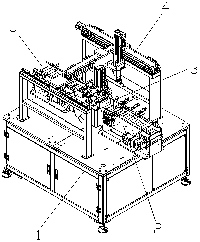
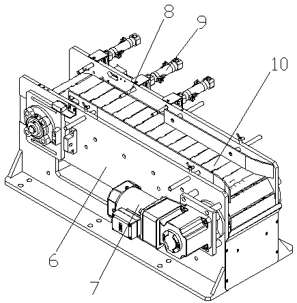
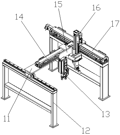
[0030] Such as Figure 1-Figure 7 As shown, the structure of the present invention is: a kind of pneumatic grinder that conveniently adjusts the grinding angle, and it comprises frame 1, the conveying device that is arranged on frame 1, power distribution control box, and described conveying device is formed by feeding device 2 Composed of a discharge device 5, a clamping and rotating mechanism 3 is arranged between the feeding device 2 and the discharging device 5, and a feeding mechanism 4 is arranged on the frame 1 above the clamping and rotating mechanism 3, so that The power components in the fee...


PUM


Abstract

The invention relates to a polishing machine, in particular to a pneumatic polishing machine with the conveniently-adjusted polishing angle. The pneumatic polishing machine comprises a rack, a conveying device and a power distribution control cabinet, the conveying device and the power distribution control cabinet are arranged on the rack, the conveying device is composed of a feeding device and adischarging device, a clamping rotation mechanism is arranged between the feeding device and the discharging device, a feeding mechanism is arranged at the position, above the clamping rotation mechanism, of the rack, and power components in the feeding device, the discharging device, the clamping rotation mechanism and the feeding mechanism are electrically connected with the power distributioncontrol cabinet; and automatic feeding and discharging of workpieces are achieved through the feeding device and the discharging device, the clamping rotation mechanism is used for fixing the workpieces and automatically adjusting the polishing angle during polishing, and polishing in different directions is achieved.

Description

technical field [0001] The invention relates to a grinding machine, in particular to a pneumatic grinding machine which can conveniently adjust the grinding angle. Background technique [0002] The universal joint refers to the use of spherical devices to achieve shaft power output in different directions. It is also a very important part of the car. The combination of the universal joint and the transmission shaft is called the universal joint transmission device. On rear-wheel drive vehicles, the universal joint drive is installed between the output shaft of the transmission and the input shaft of the drive axle final drive, while the drive shaft is omitted for vehicles with front-engine front-wheel drive, and the universal joint is installed on the drive shaft that is responsible for driving It is also responsible for steering between the front axle half shaft and the wheel. The cross shaft is a component that realizes variable-angle power transmission. It is used to chan...

Claims


Application Information

Patent Timeline
Patent Type & Authority Applications(China)
IPC IPC(8): B24B19/00B24B41/06B24B47/00B24B41/00B24B49/00B24B47/20
CPCB24B19/00B24B41/005B24B41/06B24B47/00B24B47/20B24B49/00
Inventor 苗强
Owner DONGGUAN UNIV OF TECH
Why Eureka
Try Eureka