Torque directional distribution electric drive axle based on double-rotor motor

A dual-rotor motor and electric drive technology, applied in the direction of electric power device, power device, axle, etc., can solve the problems affecting the execution effect and quality of torque directional distribution, limited clutch locking torque, high system volume and quality, etc., to achieve Good product process inheritance, improved turning maneuverability, and high system integration

Pending Publication Date: 2018-07-20
JILIN UNIV
View PDF7 Cites 5 Cited by
  • Summary
  • Abstract
  • Description
  • Claims
  • Application Information

AI Technical Summary

Problems solved by technology

[0005] Currently, this technology is used in some high-end sports cars and SUVs in the form of torque directional distribution bevel gear differentials, such as Honda's super four-wheel drive system (SH-AWD) and Mitsubishi's super active yaw control system ( SAYC), etc., but this technology has not been widely used in electric vehicles. In addition, the existing torque directional distribution bevel gear differential technology used in traditional four-wheel drive vehicles often relies on the arrangement of multiple discs in the drive axle. Planetary gear mechanism controlled by electromagnetic or hydraulic clutch to achieve lateral transfer and distribution of torque
Increased system power consumption due to slip losses when clutch engages and disengages
Moreover, the clutch lock-up torque is limited, and there is a response lag in the action, which affects the execution effect and quality of torque directional distribution
In addition, multiple sets of planetary gear mechanisms also lead to high system volume and quality, making space layout difficult

Method used


Image

  • Torque directional distribution electric drive axle based on double-rotor motor
  • Torque directional distribution electric drive axle based on double-rotor motor
  • Torque directional distribution electric drive axle based on double-rotor motor

Examples


Embodiment Construction

[0041] The present invention will be further described in detail below in conjunction with the accompanying drawings, so that those skilled in the art can implement it with reference to the description.

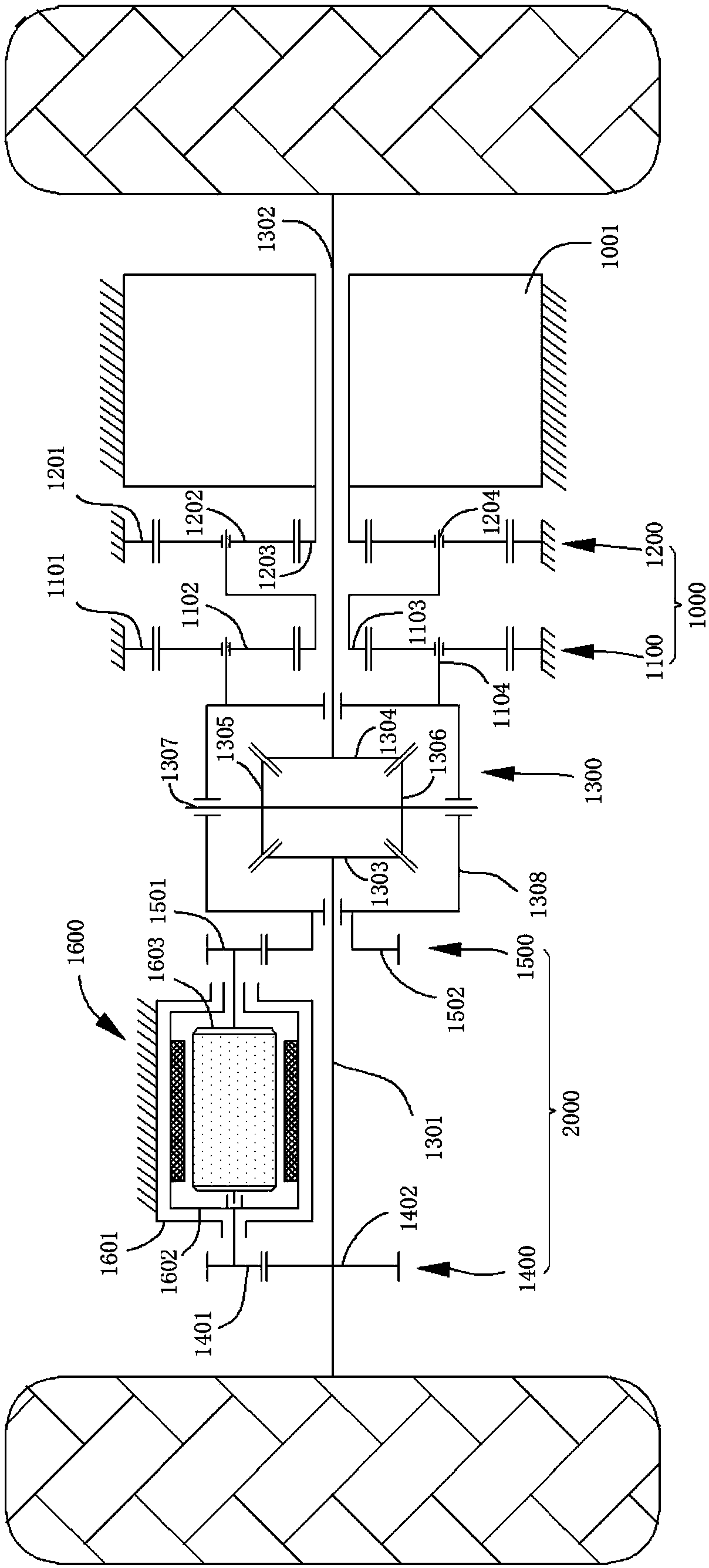
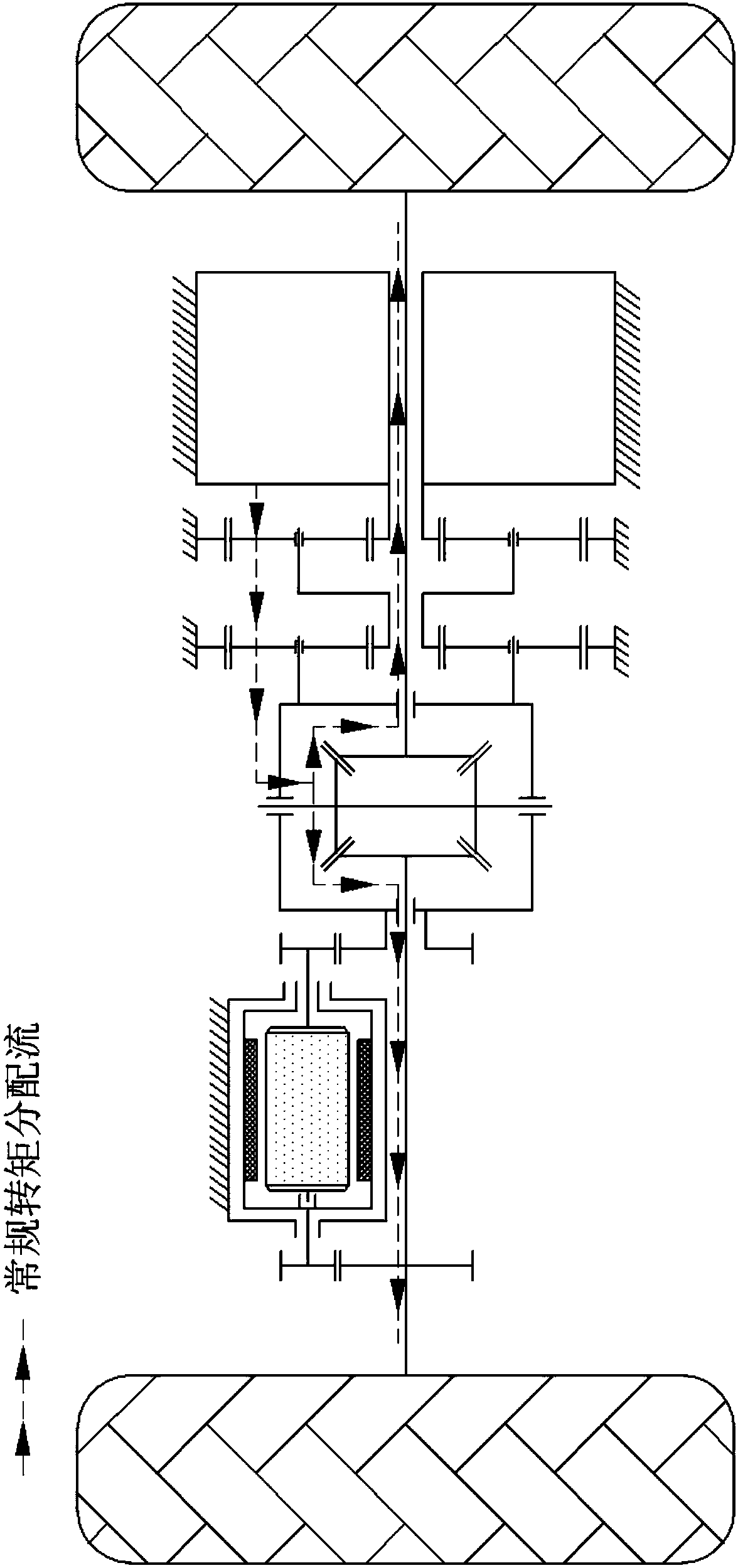
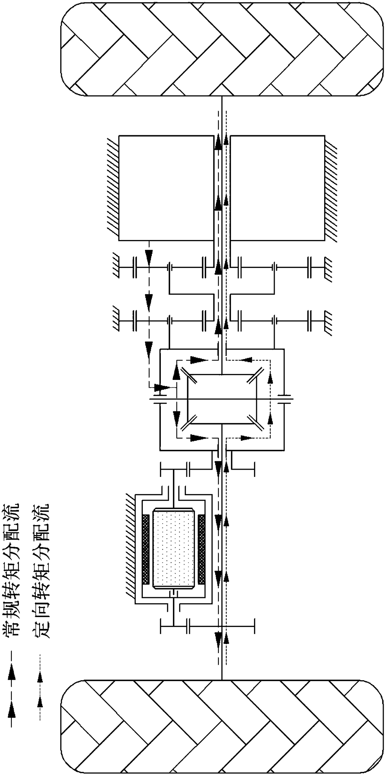
[0042] Such as figure 1 As shown, the present invention provides a torque directional distribution electric transaxle based on a dual-rotor motor, which mainly consists of a torque directional distributor 2000, a bevel gear differential mechanism 1300, a main drive motor reduction mechanism 1000 and a main drive motor 1001 constitute.

[0043] The torque directional distributor 2000 is located on the left side of the drive axle (it can also be exchanged with the main power source assembly composed of the main drive motor 1001 and the main drive motor reduction mechanism 1000, and it is arranged on the right side of the drive axle), mainly by A counter-rotating double-rotor motor 1600 , a first output end gear transmission mechanism 1400 and a second output end gear transmiss...


PUM


Abstract

The invention discloses a torque directional distribution electric drive axle based on a double-rotor motor. The drive axle comprises a main drive motor and the relatively-rotating type double-rotor motor, wherein the output end of the main drive motor is connected with a shell of a bevel gear differential mechanism through a speed reduction mechanism; the relatively-rotating type double-rotor motor comprises an outer rotor and an inner rotor which are coaxially arranged and rotate relatively; a first output end drive gear of a first output end gear transmission mechanism is fixedly connectedwith the output end of the outer rotor of the double-rotor motor, and a first output end driven gear is connected with a first axle shaft; a second output end drive gear of a second output end gear transmission mechanism is fixedly connected with the output end of the inner rotor of the double-rotor motor, and a second output end driven gear is fixedly connected with the shell of the bevel gear differential mechanism; and the first output end gear transmission mechanism and the second output end gear transmission mechanism have the same transmission ratio. By the adoption of the provided torque directional distribution electric drive axle based on the double-rotor motor, torque directional distribution of wheels on the two sides can be achieved without a clutch, the action response is madequickly, and the integration degree is high.

Description

technical field [0001] The invention belongs to the technical field of electric vehicle transmission, and in particular relates to a torque-oriented distribution electric drive axle based on a double-rotor motor. Background technique [0002] In recent years, with the improvement of people's living standards and the continuous advancement of technology, people have put forward higher and higher requirements for the quality of cars, from the initial demand only as a means of transportation to the safety, comfort, economy, etc. In terms of demand for performance and driving pleasure, people's demand for high-performance cars is also increasing year by year. Therefore, investment in research and development of high-performance vehicles is also very necessary. [0003] Electric vehicles are an important development direction for future transportation to adapt to energy conservation and emission reduction. They have received attention from various countries and have achieved goo...

Claims


Application Information

Patent Timeline
Patent Type & Authority Applications(China)
IPC IPC(8): B60B35/12B60K1/02B60K17/04B60K17/16
CPCB60B35/125B60K1/02B60K17/04B60K17/165
Inventor 王军年杨斌
Owner JILIN UNIV
Why Eureka
Try Eureka