Steering and suspension system

A technology of suspension system and steering gear, which is applied in the direction of suspension, elastic suspension, steering mechanism, etc. It can solve the problems of unreliable reliability, practical use, high technical difficulty, etc., and achieve improved dynamic characteristics and good ride feeling Effect

Pending Publication Date: 2018-07-20
上海艾高实业有限公司
View PDF0 Cites 2 Cited by
  • Summary
  • Abstract
  • Description
  • Claims
  • Application Information

AI Technical Summary

Problems solved by technology

[0003] In the existing technology, the four-wheel independent steering system based on the steering-by-wire technology has the following disadvantages: the steering-by-wire technology is not yet mature, and its reliability has yet to be verified, and it has not yet reached the level where it can be safely promoted and applied on vehicles; In addition to the obvious high reliability requirements of steering technology, the coordinated control of kinematics and dynamics of the wheels on the left and right sides is also extremely demanding, wh...

Method used


Image

  • Steering and suspension system
  • Steering and suspension system
  • Steering and suspension system

Examples


Embodiment 1

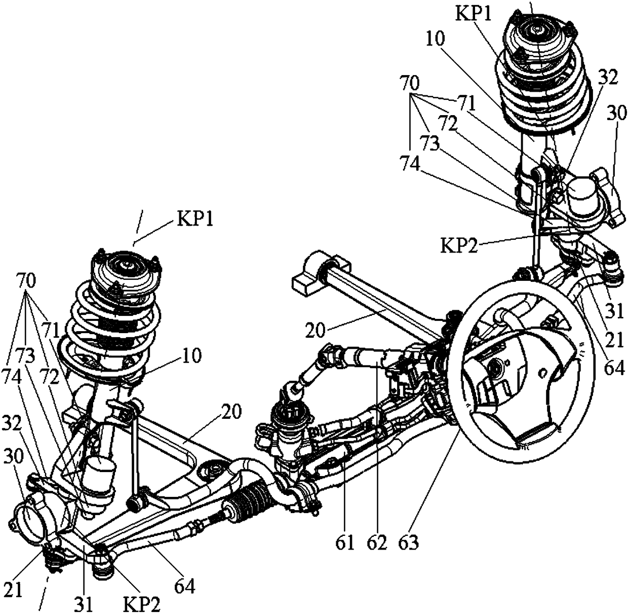
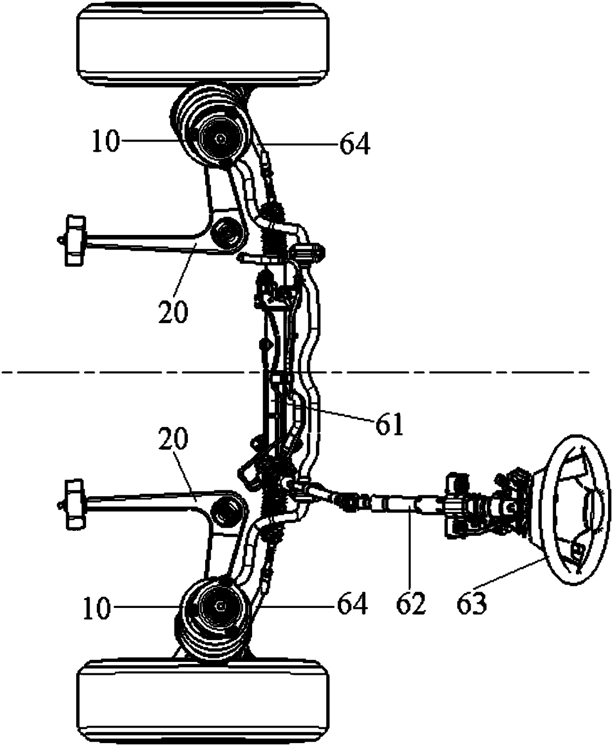
[0078] see Figure 1~6 As shown, in the first specific embodiment of the present invention, the steering and suspension system of the present invention includes: a spring strut 10, a pin shaft 40, a lower guide ball joint 21, a swing arm 20, a wheel bracket 30, a first Steering knuckle arm 31, steering tie rod 64, steering gear 61, wheel steering gear 70; wherein,

[0079] The lower end of the spring strut 10 is fixedly connected with the upper end of the pin shaft 40, and the lower end of the pin shaft 40 is connected with the swing arm 20 through the lower guide ball joint 21; The line forms the first kingpin axis KP1; the pin axis of the pin shaft 40 is the second kingpin axis KP2, and the second kingpin axis KP2 coincides with the first kingpin axis KP1;

[0080] One end of the first steering knuckle arm 31 is fixedly connected to the pin shaft 40 or the spring strut 10, and the other end of the first steering knuckle arm 31 is connected with the steering gear 61 through ...

Embodiment 2

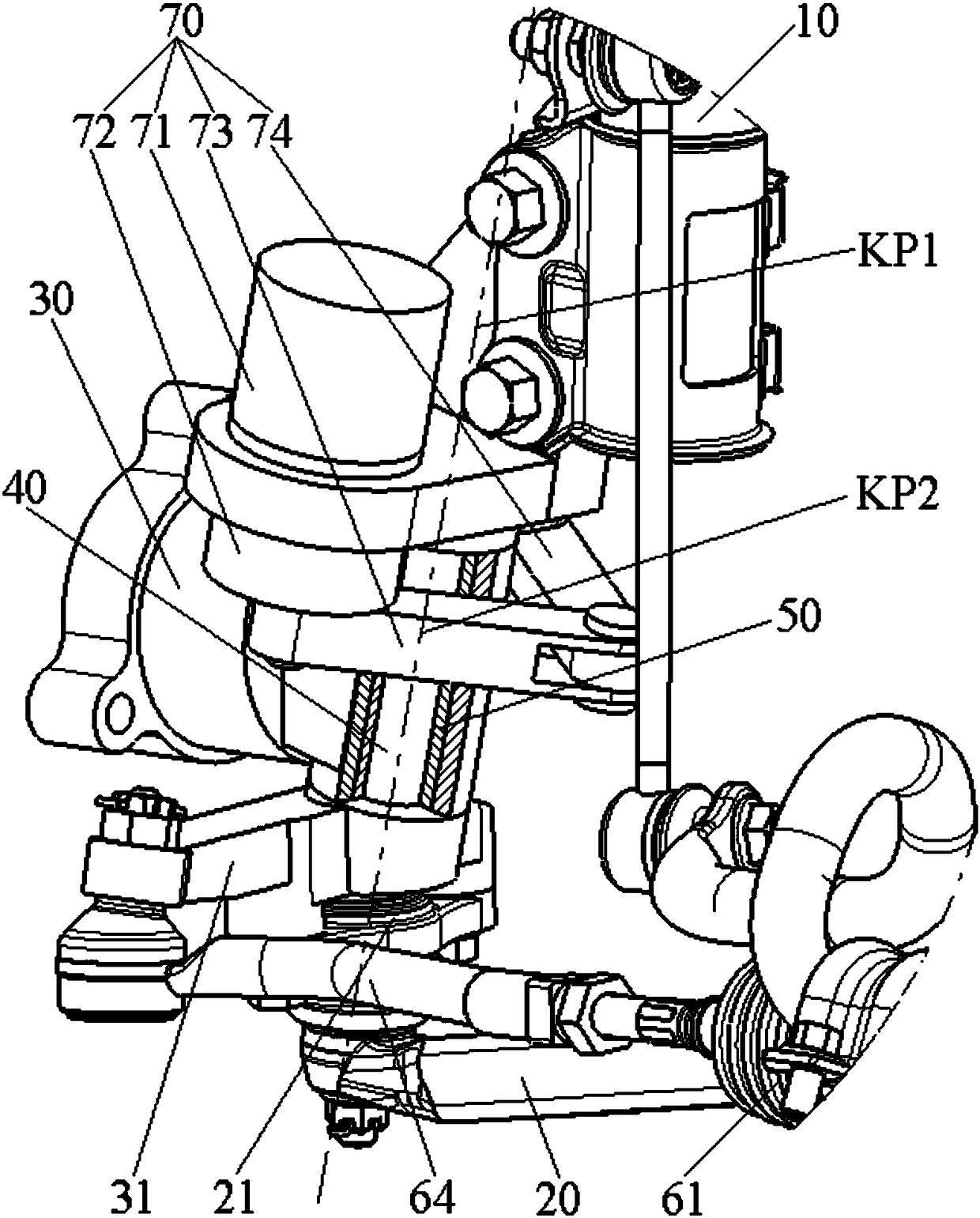
[0099] refer to Figure 7 and Figure 8 , in the second specific embodiment of the present invention, the steering and suspension system of the present invention includes: a spring strut 10, an upper guide element 51, a lower guide ball joint 21, a swing arm 20, a wheel bracket 30, a first steering Knuckle arm 31, steering tie rod 64, steering gear 61 and wheel steering gear 70; wherein,

[0100] The lower end of the spring strut 10 is connected with the upper end of the wheel bracket 30 through the upper guide element 51, the lower end of the wheel bracket 30 is connected with the swing arm 20 through the lower guide ball joint 21, the upper fulcrum of the spring strut 10 is connected with the lower guide ball The line connecting the center of the hinge 21 forms the first kingpin axis KP1; the upper guide element 51 and the lower guide ball hinge 21 form the second kingpin axis KP2;

[0101] One end of the first steering knuckle arm 31 is fixedly connected to the spring str...


PUM


Abstract

The invention discloses a steering and suspension system. The steering and suspension system comprises spring struts, wheel brackets, steering engines and wheel-side steering engines, wherein the connecting lines between upper supporting points of the spring struts and the centers of lower guiding spherical hinges forms first king pin axes; upper guiding elements and the lower guiding spherical hinges form second king pin axes or pin shaft axes coincided with the first king pin axes are used as the second king pin axes; the steering engines are used for driving the spring struts to rotate around the first king pin axes; and the wheel-side steering engines are used for driving the wheel brackets to rotate around the second king pin axes. According to the steering and suspension system, as wheels are driven by the steering engines to steer during the running of a vehicle, and the wheels are driven by the wheel-side steering engines to steer during parking of the vehicle, the steering performance of the vehicle during running is guaranteed under a condition of obviously reducing requirements on a steering control system and the parking process is also simplified. In addition, the steering and suspension system can also be simplified by eliminating the steering engines; and the steering and suspension system is used for realizing non-steering rear axles of automobiles.

Description

technical field [0001] The invention relates to the field of motor vehicles, in particular to a steering and suspension system, in particular to a steering and suspension system of an automobile chassis. Background technique [0002] The wheel steering angle range of conventional cars is usually ±35°, and some special-purpose vehicles can reach ±45°. Obviously, the larger the maximum steering angle of the wheel, the smaller the minimum steering radius of the vehicle, and the better its low-speed steering performance (including parking performance). In the prior art, the maximum steering angle of the steering wheel of a 4WD / 4WS (that is, four-wheel independent drive / four-wheel independent steering) vehicle to the inside or outside can reach 90°, realizing in-situ steering, fixed-point steering and lateral driving, etc. The function greatly improves the maneuverability of the vehicle, especially the parking performance in a small space, and significantly simplifies the parkin...

Claims


Application Information

Patent Timeline
IPC IPC(8): B62D5/04B62D9/00B62D7/20B60G11/14
CPCB62D5/0418B62D5/0421B62D7/20B62D9/00B60G11/14B60G2200/14B60G2204/1244B60G2204/148B60G2204/4302
Inventor 蒋洪波葛桦楠
Owner 上海艾高实业有限公司
Why Eureka
Try Eureka