Down-hole fluid heater for non-conventional energy

An unconventional heater technology, applied in the direction of production fluid, wellbore/well components, isolation devices, etc., can solve the problems of large fluid pressure loss, poor heater outlet sealing effect, low heating rate, etc., to reduce pressure loss , Improve the sealing effect of the outlet and the effect of increasing the heating rate

Active Publication Date: 2018-07-20
JILIN UNIV
View PDF16 Cites 5 Cited by
  • Summary
  • Abstract
  • Description
  • Claims
  • Application Information

AI Technical Summary

Problems solved by technology

[0006] The purpose of the present invention is to provide a downhole fluid heater for unconventional energy, which solves the problems of low heating rate, large fluid pressure loss and poor sealing effect of heater outlet in existing downhole heaters.

Method used


Image

  • Down-hole fluid heater for non-conventional energy
  • Down-hole fluid heater for non-conventional energy

Examples


Embodiment Construction

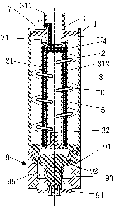
[0024] see figure 1 As shown, a downhole fluid electric heater for unconventional energy includes a shell 1, a continuous spiral baffle 2, a central tube 3, an insulating layer 4, an eddy current coil 5, a high-temperature heat pipe 6, a junction box 7, and a cooling rod 8 in one-way valve 9;

[0025] The upper part of the housing 1 is provided with a tapered internal thread, which is used to connect with the outer central pipe 31 and plays a sealing role; 31 joints are sealed.

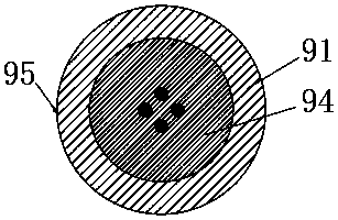
[0026] The lower part of the housing 1 is provided with a tapered external thread for connecting with the one-way valve 9; the lower part of the housing 1 is provided with a tapered hole for cooperating with the upper valve body 92 to seal the outlet of the heater to prevent backflow of downhole fluid.

[0027] The continuous spiral baffle 2 and the central pipe 3 are welded as a whole, and the continuous spiral baffle 2 is welded as a whole by a single baffle. By splitting the continuous spiral ba...


PUM


Abstract

The invention discloses a down-hole fluid heater for non-conventional energy. The heater comprises a shell, a continuous spiral baffle plate, a center pipe, an insulation layer, an eddy current coil,a heat dissipation rod, a high temperature hot pipe, a wiring box and a one-way valve. According to the down-hole fluid heater for non-conventional energy, fluid is indirectly heated by using an eddycurrent effect, and through combination of boiling heat transfer of liquid-state sodium in the center pipe, the high temperature hot pipe and the continuous spiral baffle plate, the speed of heating the down-hole fluid is increased. In the down-hole operation process of a heater, by changing input current, secondary sealing of a heater outlet is achieved, and the down-hole fluid can be effectivelyprevented from flowing back into the heater.

Description

technical field [0001] The invention relates to a downhole fluid heater for unconventional energy, in particular to the fields of unconventional energy such as oil shale, heavy oil, heavy oil, oil sand, and natural gas hydrate. Background technique [0002] The current utilization technologies of underground hydrocarbon resources are divided into surface utilization technologies and in-situ conversion technologies. Surface utilization technology is a relatively mature underground hydrocarbon resource development technology at present, but surface utilization technology has disadvantages such as high mining costs, large air and groundwater pollution, and large water consumption; it is not suitable for deep hydrocarbon resource exploitation. In-situ conversion technology refers to the in-situ heat treatment of underground hydrocarbon deposits to pyrolyze underground hydrocarbon resources. The in-situ conversion technology has the advantages of not damaging the surface, no pol...

Claims


Application Information

Patent Timeline
Patent Type & Authority Applications(China)
IPC IPC(8): E21B43/24E21B36/04
CPCE21B36/04E21B43/2401
Inventor 郭威王振东孙友宏李强邓孙华张鹏宇赵帅陈强刘召
Owner JILIN UNIV
Why Eureka
Try Eureka