Supercharge Your Innovation With Domain-Expert AI Agents!

Large-aperture valve flow rate test system pipeline bracket device

A valve flow and pipeline support technology, applied in the direction of pipeline supports, hoses, pipes, etc., can solve the problems of difficult adjustment of support height, large frictional resistance, and difficulty in ensuring pipeline stability, so as to improve installation stability and improve The effect of lifting balance and ensuring stability

Pending Publication Date: 2018-07-20
HEFEI GENERAL MACHINERY RES INST
View PDF6 Cites 4 Cited by
  • Summary
  • Abstract
  • Description
  • Claims
  • Application Information

AI Technical Summary

Problems solved by technology

[0002] The valve flow resistance test system is an important device for testing the performance of the valve. During the construction of the test system, the pipeline is generally erected with a bracket. However, due to installation errors or foundation deviations, there will be a deviation between the height of the bracket and the installation height of the pipeline. The height of the existing bracket is difficult to adjust; during the test process, due to the different structural lengths of valves with different pressure levels, it is necessary to move and lift the installation pipeline to adapt to the installation space required by the tested valve, so as to realize the disassembly and assembly of different types of valves At the same time, because the large-diameter pipeline test system usually adopts the method of replacing the reduced-diameter pipe to achieve the coverage of the full-diameter pipeline, when testing part-caliber valves, it is necessary to replace the main pipeline at both ends of the test valve with the reduced-diameter pipeline, and move , lifting to adjust the centering performance of the variable diameter pipes at both ends
However, manual adjustment of the existing brackets is difficult to ensure the alignment of the pipelines installed at both ends, and the frictional resistance between the pipelines and the brackets during the axial movement is relatively large, resulting in inconvenient disassembly and assembly of the valves and stability of the pipelines. Difficult to guarantee

Method used


Image

  • Large-aperture valve flow rate test system pipeline bracket device
  • Large-aperture valve flow rate test system pipeline bracket device
  • Large-aperture valve flow rate test system pipeline bracket device

Examples


Embodiment Construction

[0029] Now illustrate structural features of the present invention in conjunction with accompanying drawing:

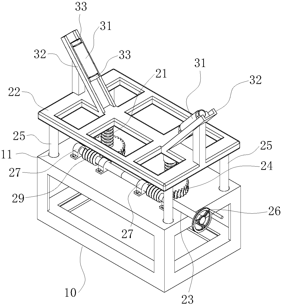
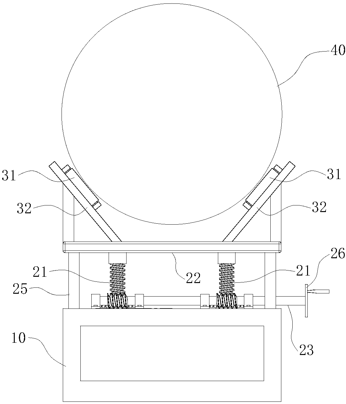
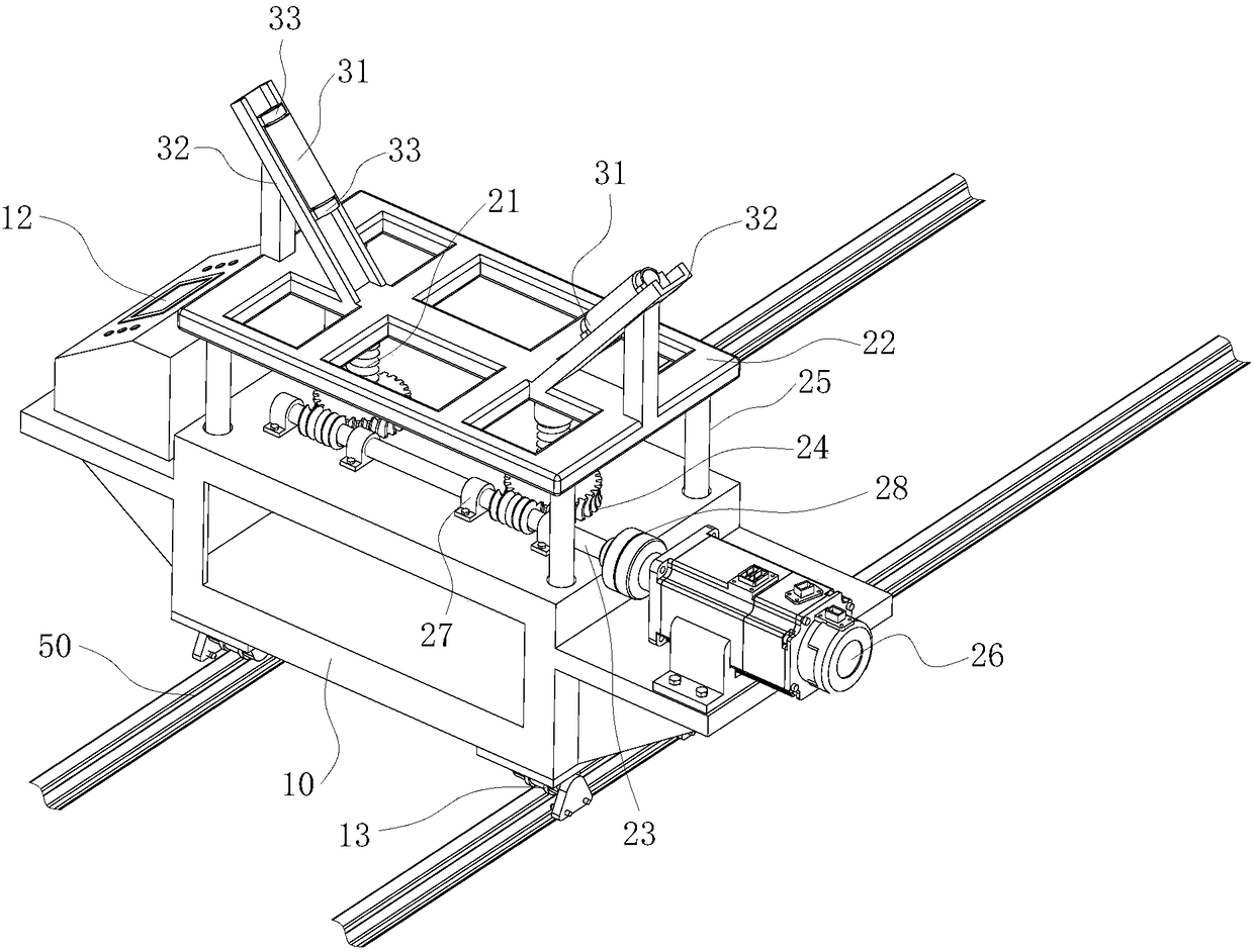
[0030] Such as figure 1 , 2 , 3: the present invention includes a guide rail 50, a base 10 installed on the guide rail 50 and movable along the guide rail 50, and a pipeline lifting mechanism and a pipeline support mechanism located above the base 10;

[0031] The pipeline lifting mechanism includes a lifting stud 21, a worm gear pair and a bracket body 22 installed on the upper end of the lifting stud 21. The worm 23 is horizontally installed on the base 10 through a supporting bearing 27. The worm gear 24 is sleeved on the lifting stud 21 and threadedly matched with the lifting stud 21, and the secondary action of the worm gear drives the lifting stud 21 to move up and down.

[0032] The pipeline support mechanism includes a plurality of cylindrical rollers 31 installed above the bracket body 22 and used to support the pipeline 40 , the cylindrical rollers 31 are ...


PUM

PropertyMeasurementUnit
Slopeaaaaaaaaaa

Abstract

The invention relates to a large-aperture valve flow rate test system pipeline bracket device which comprises a base which walks along rails, a pipeline lifting mechanism and a pipeline supporting mechanism; the pipeline lifting mechanism comprises lifting studs, a worm-gear pair and a bracket body installed at the upper ends of the lifting studs; a worm is horizontally installed on the base; wormgears sleeve the lifting studs respectively and are in threaded matching with the lifting studs respectively; the worm-gear pair moves to drive the lifting studs to move up and down; the pipeline supporting mechanism comprises multiple cylinder rolling wheels which are installed above the bracket body and are used for supporting a pipeline; and the axial direction of each cylinder rolling wheel is installed perpendicular to the axial direction of the pipeline and is tangential to the side surface of the pipeline. By adopting the large-aperture valve flow rate test system pipeline bracket device provided by the invention, the worm rotates to drive rotation of the worm gears, the worm gears rotate to realize up and down movement of the lifting studs while driving threaded matching of the lifting studs and the worm gears, and then regulation of a height of the bracket body is realized; and the cylinder rolling wheels reduce friction with the pipeline when the pipeline performs axial movement and enable the pipeline to be liable to move and good in stability.

Description

technical field [0001] The invention relates to the field of valve test devices, in particular to a pipeline support device for a large-diameter valve flow test system. Background technique [0002] The valve flow resistance test system is an important device for testing the performance of the valve. During the construction of the test system, the pipeline is generally erected with a bracket. However, due to installation errors or foundation deviations, there will be a deviation between the height of the bracket and the installation height of the pipeline. The height of the existing bracket is difficult to adjust; during the test process, due to the different structural lengths of valves with different pressure levels, it is necessary to move and lift the installation pipeline to adapt to the installation space required by the tested valve, so as to realize the disassembly and assembly of different types of valves At the same time, because the large-diameter pipeline test sy...

Claims


Application Information

Patent Timeline
IPC IPC(8): F16L3/02F16L3/01F16L3/18F16L3/16
CPCF16L3/01F16L3/02F16L3/16F16L3/18
Inventor 张继伟王剑黄健范宜霖程红晖彭林雷艳
Owner HEFEI GENERAL MACHINERY RES INST
Features
  • R&D
  • Intellectual Property
  • Life Sciences
  • Materials
  • Tech Scout
  • Unparalleled Data Quality
  • Higher Quality Content
  • 60% Fewer Hallucinations
Learn More