
Air energy condenser or evaporator

A technology for condensers and evaporators, which is applied to evaporators/condensers, refrigerators, refrigeration components, etc., and can solve the problems of reducing the temperature range of refrigeration or heating, and the heat exchange effect is not fully exerted, etc.

Inactive Publication Date: 2018-07-20
张诗华
View PDF0 Cites 0 Cited by
  • Summary
  • Abstract
  • Description
  • Claims
  • Application Information

AI Technical Summary

Problems solved by technology

According to the principle of heat conduction: heat is transferred from high temperature to low temperature. Since the metal tubes in the existing condenser or evaporator are not connected sequentially in the direction of wind passing through, a turbulent temperature field is formed during heat conversion. As a result, When the medium such as refrigerant passes through the metal tube, the heat exchange effect of each stage is not fully exerted, and the temperature range of cooling or heating is relatively reduced.

Method used


Image

  • Air energy condenser or evaporator
  • Air energy condenser or evaporator

Examples


Embodiment Construction

[0013] The present invention will be further described below in conjunction with drawings and embodiments.

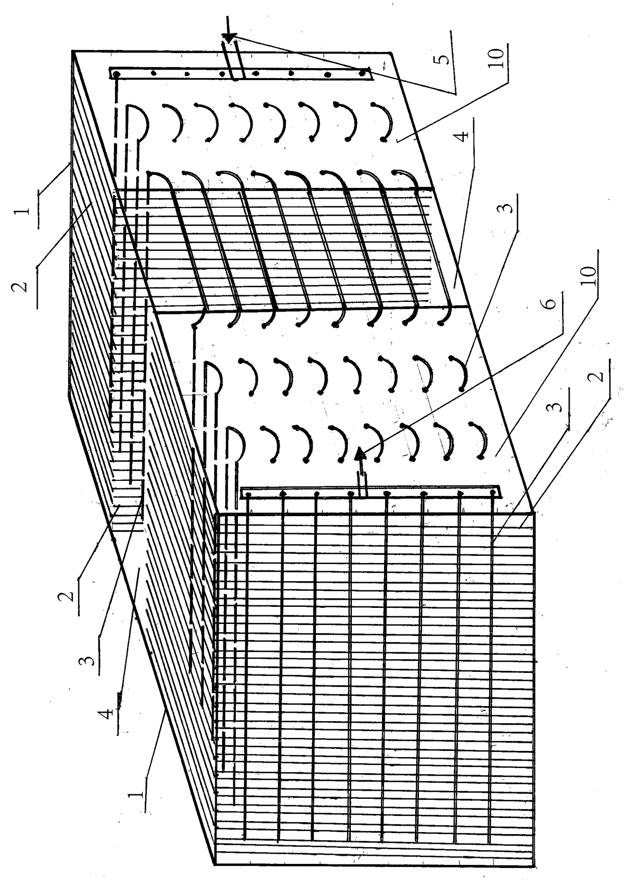
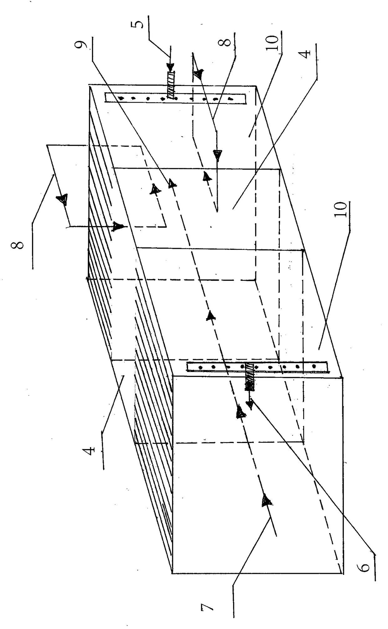
[0014] Such as figure 1 , figure 2 As shown, the air energy condenser or evaporator includes bracket (1), metal sheet (2), metal pipe (3), monomer (10), refrigerant inlet (5), refrigerant outlet (6), and return air inlet (4), air inlet (7), air outlet (9) and return air (8), consisting of bracket (1) connected with metal sheet (2), metal sheet (2) connected with metal pipe (3) to form one or more The monomers (10), set the gap between the monomers (10) as the return air inlet (4), the return air inlet (4) enters the return air (8), and the metal pipes (3) in each monomer (10) Connect in layers in order from left to right, one end of the connected metal pipe (3) is the refrigerant inlet (5), the other end of the connected metal pipe (3) is the refrigerant outlet (6), and the refrigerant inlet is set One end of (5) is the air outlet (9), and the other end of the refri...


PUM


Abstract

The invention discloses an air energy condenser or evaporator which comprises a support, metal sheets, metal pipes, one or more single bodies, return air inlets, a refrigerant inlet, a refrigerant outlet, an air inlet and an air outlet. The support, the metal sheets and the metal pipes are connected to form the single bodies, the gaps between the single bodies are arranged as the return air inletswhich return air enters, the metal pipes in the single bodies are sequentially connected in a layered mode from left to right, one end of the connected metal pipes is arranged as the refrigerant inlet, the other end of the connected metal pipes is arranged as the refrigerant outlet, one end of the refrigerant inlet is arranged as the air outlet, and one end of the refrigerant outlet is arranged as the air inlet. The air energy condenser or evaporator is characterized in that the single bodies formed by connecting the metal sheets with the metal pipes and the return air inlets are connected toform the air energy condenser or evaporator.

Description

technical field [0001] The invention relates to an air energy equipment system, in particular to an air energy condenser or evaporator. Background technique [0002] Air energy is driven by a small amount of electricity to drive the compressor, which continuously compresses the refrigerant and other media to flow through the metal tube, and according to the heat release and heat absorption phenomena in the cycle of the gas turning into liquid, and the liquid turning into gas again, so as to realize the Thermal energy transfer enables twice the electric transfer to produce several times the energy of electric heat, and transforms it into hot air and hot water or cold air and cold water as needed. Because of its high efficiency, environmental protection, and energy saving, it has been used in many fields. However, the condenser or evaporator in the existing air energy equipment is a section of multi-layer metal tube piercing the metal sheet structure, and the metal tubes are i...

Claims


Application Information

Patent Timeline
Patent Type & Authority Applications(China)
IPC IPC(8): F25B30/06F25B39/02F25B39/04
CPCF25B30/06F25B39/02F25B39/04
Inventor 不公告发明人
Owner 张诗华
Learn More