
Dynamic micro-cantilever array cyclic scanning system based on rotary table

A micro-cantilever, cyclic scanning technology, applied in measurement devices, instruments, optical devices, etc., can solve problems such as jamming, save space, and realize the effect of automatic switching of optical paths

Active Publication Date: 2018-07-20
ANHUI UNIV OF SCI & TECH
View PDF5 Cites 7 Cited by
  • Summary
  • Abstract
  • Description
  • Claims
  • Application Information

AI Technical Summary

Problems solved by technology

[0004] In the patent document with the publication number CN203758529, a "micro-cantilever beam deflection detection system based on the micro-cantilever beam array sensor reflected by the plane mirror" is disclosed, which uses a voice coil motor to drive the plane mirror to perform reciprocating swing to make the laser beam emitted by the laser Perform reciprocating translation or rotation to scan each beam on the array. The system has a simple structure and is easy to implement; however, the voice coil motor drives the plane mirror to reciprocate. Caton will appear

Method used


Image

  • Dynamic micro-cantilever array cyclic scanning system based on rotary table
  • Dynamic micro-cantilever array cyclic scanning system based on rotary table
  • Dynamic micro-cantilever array cyclic scanning system based on rotary table

Examples


Embodiment Construction

[0031] The present invention will be further explained by specific examples below.

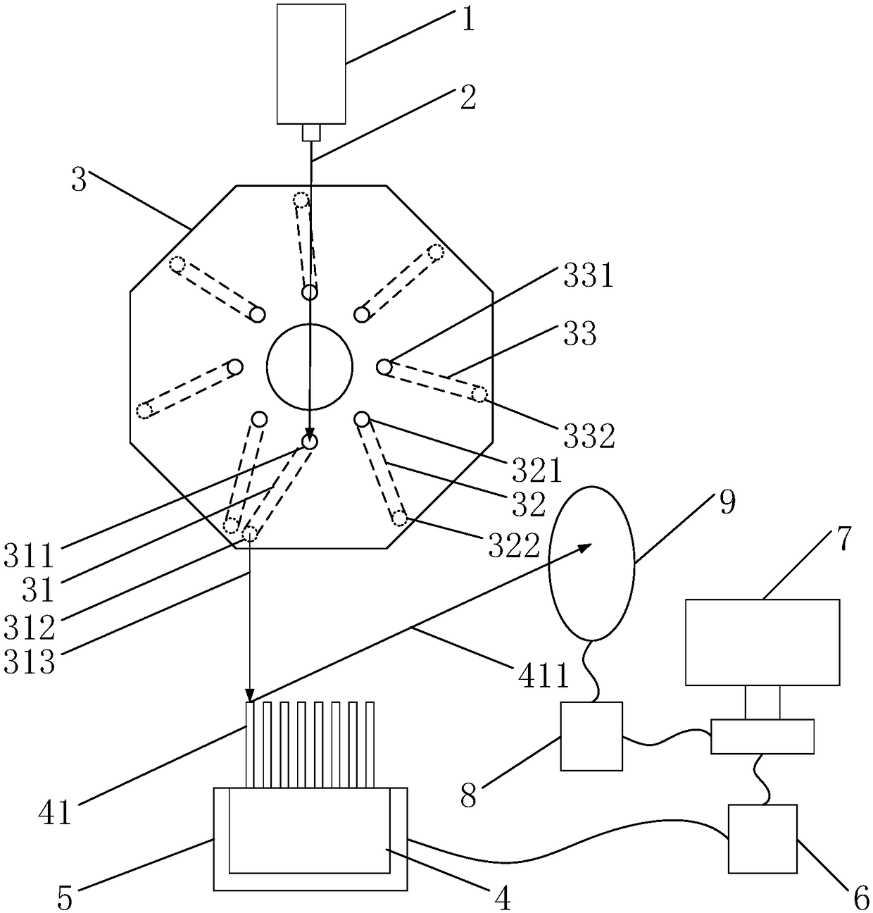
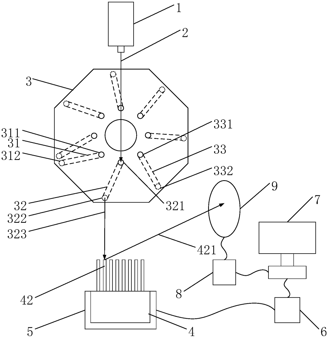
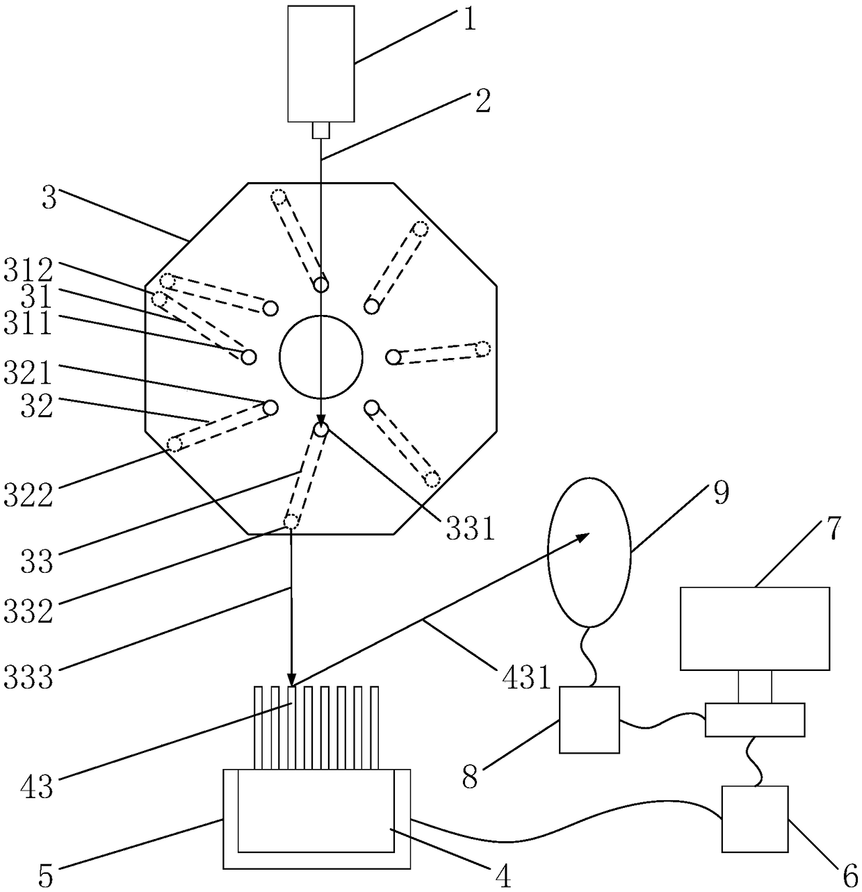
[0032] see figure 1 , figure 2 , image 3 , Figure 4 , Figure 5 In this embodiment, the structural form of a dynamic micro-cantilever array cyclic scanning system based on a turntable is: the structural form of a cyclic scanning system composed of eight scanning units is set as follows: a laser 1, a turntable 3, a micro-cantilever beam Array 4, piezoelectric ceramic driver 5, function signal generator 6, photoelectric position sensitive detector 9, data acquisition card 8, computer 7;

[0033] The laser 1 is installed perpendicular to the upper surface of the turntable 3, the micro-cantilever array 4 is installed under the turntable 3 and the micro-cantilever array 4 is fixed on the surface of the piezoelectric ceramic driver 5, and the piezoelectric ceramic driver 5 and the function signal generator 6 is connected, the function signal generator 6 is connected with the computer 7, and ...


PUM

PropertyMeasurementUnit
Wavelengthaaaaaaaaaa

Abstract

The invention relates to a dynamic micro-cantilever array cyclic scanning system based on a rotary table, and the system is characterized in that the system comprises a laser, the rotary table, a micro-cantilever array, a piezoelectric ceramic driver, a function signal generator, a photoelectric position sensitive detector, a data collection card, and a computer; the laser is installed in a mannerof being perpendicular to the upper surface of the rotary table; the micro-cantilever array is disposed below the rotary table, and the micro-cantilever array is fixed on the surface of the piezoelectric ceramic driver; the piezoelectric ceramic driver is connected with the function signal generator, and the function signal generator is connected with the computer; the photoelectric position sensitive detector is installed slantwise above the micro-cantilever array; the photoelectric position sensitive detector is connected with the data collection card, and the data collection card is connected with the computer. The system achieves the cyclic scanning of the micro-cantilever array through enabling the rotary table to make cyclic rotation in one direction, achieves the automatic switching of an optical path, and cannot cause a stuck phenomenon. Moreover, a fiber is installed in the rotary table, thereby saving the space.

Description

technical field [0001] The invention relates to the field of micro-cantilever beam scanning, in particular to a turntable-based dynamic micro-cantilever beam array cyclic scanning system. Background technique [0002] With the development of science and technology, the sensing technology is becoming more and more mature, and the micro-cantilever sensing technology has been applied in the fields of biology and chemistry. However, the relatively mature micro-cantilever sensing technology currently uses a single micro-cantilever beam. When multiple single micro-cantilever beams are detected, the difference in environmental factors will cause errors in the detection results. Using the micro-cantilever array to detect can effectively reduce this error, because the micro-cantilever array itself can provide the reference beam needed for the experiment, and the environmental conditions are the same. Therefore, it is very necessary to study the micro-cantilever array. [0003] The ...

Claims


Application Information

Patent Timeline
IPC IPC(8): G01B11/16
CPCG01B11/18
Inventor 薛长国张飞牛晓燕张涛杨帆宋晓闵凡飞
Owner ANHUI UNIV OF SCI & TECH
Learn More