Spatial phase-shifting interferometer

A phase-shift interference and space technology, applied in the direction of instruments, measuring devices, and optical devices, can solve the problems of many optical components, complex structures, and long time for image acquisition, and achieve the effect of integration and fewer optical components

Pending Publication Date: 2018-07-20
GUANGZHOU XUNZHI MACHINERY
View PDF0 Cites 1 Cited by
  • Summary
  • Abstract
  • Description
  • Claims
  • Application Information

AI Technical Summary

Problems solved by technology

[0004] The method of phase shift is usually divided into time phase shift and space phase shift. The time phase shift is to calculate the phase by collecting several pictures in the time series; the space phase shift is to collect a picture at the same time, which contains different Spatial phase information, the phase can be calculated with one image; time phase shift technology has the following disadvantages: complex structure, many distribution of optical components; long image acquisition time, which is not conducive to rapid detection

Method used


Image

  • Spatial phase-shifting interferometer
  • Spatial phase-shifting interferometer

Examples


Embodiment Construction

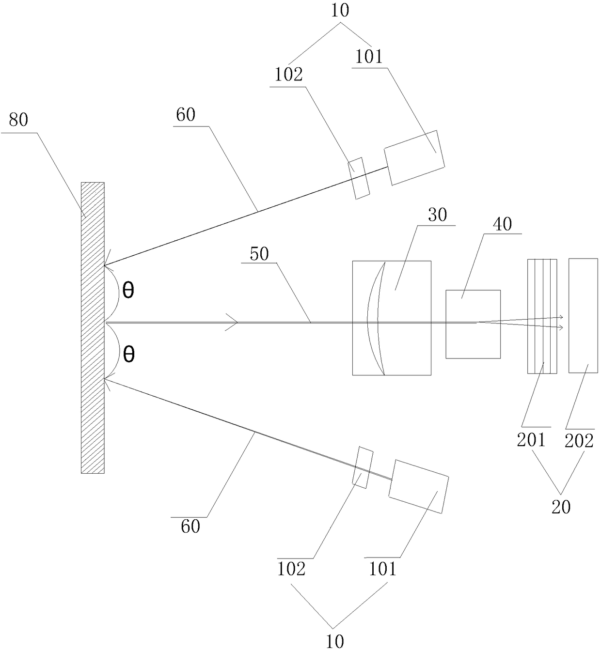
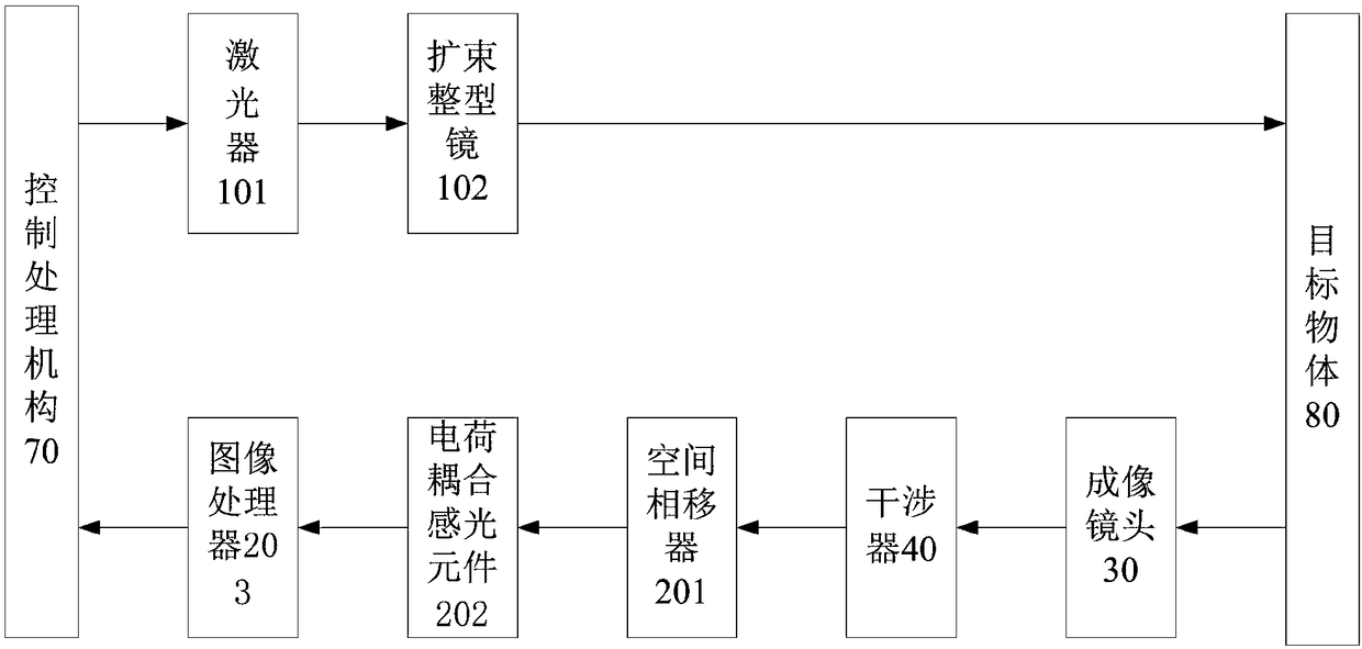
[0022] In this example, refer to figure 1 with figure 2 , a spatial phase shift interferometer, including a laser emitting mechanism 10, a laser receiving mechanism 20, an interferometer 40 and an imaging lens 30, and also includes a first coaxial line 50 and a second coaxial line 60, the first coaxial line 50 and the second coaxial line An included angle θ is formed between the two coaxial lines 60, and the included angle θ is 30°. The laser emitting mechanism 10 includes a laser 101 and a beam expander shaping mirror 102. The laser receiving mechanism 20, an interferometer 40 and an imaging lens 30 are all distributed on the first coaxial axis 50, the imaging lens 30 and the laser receiving mechanism 20 are respectively arranged on the front side and the rear side of the interferometer 40, and the laser emitting mechanism 10 is arranged on the second coaxial The line 60 is separately arranged on both sides of the imaging lens 30. When the laser emitting mechanism 10 emits ...


PUM


Abstract

The invention provides a spatial phase-shifting interferometer. The interferometer comprises laser emission mechanisms, a laser receiving mechanism, an interference device, an imaging lens, a first coaxial line and a second coaxial line, each laser emission mechanism comprises a laser and a beam-expanding shaping prism, the laser receiving mechanism, the interference device and the imaging lens are distributed on the first coaxial line, the imaging lens and the laser receiving mechanism are arranged on the front side and the rear side of the interference device respectively, and the laser emission mechanisms are arranged on the second coaxial line and arranged on the two sides of the imaging lens respectively; when the laser emission mechanisms emit laser beams, the laser beams are reflected after shining on the surface of a target object, form two ways of light beams after passing through the imaging lens and the interference device in sequence along the first coaxial line, and then are received and treated by the laser receiving mechanism. The spatial phase-shifting interferometer is simple in structure and rapid in image information collection.

Description

technical field [0001] The invention relates to an optical interference instrument, in particular to a space phase shift interferometer. Background technique [0002] The laser speckle is used as the carrier of the field change information of the measured object, and the relevant fringes of the interference speckle field generated by the measured object after being irradiated by the laser are used to detect the phase change between the front and rear of the two beams. One laser beam is expanded by the lens and Projected onto the surface of the object to be detected, the reflected light interferes with the reference beam directly projected from the laser to the camera, and a speckle field and a series of speckle images are generated on the illuminated surface; when the object moves, these speckles will Changes occur accordingly, and these changes represent the displacement field changes or deformation information on the surface of the measured object; use CCD (charge-coupled ...

Claims


Application Information

Patent Timeline
IPC IPC(8): G01B11/16G01B9/02
CPCG01B9/0203G01B9/02095G01B11/162
Inventor 黄嘉兴曾启林宁文斌游强徐志江
Owner GUANGZHOU XUNZHI MACHINERY
Why Eureka
Try Eureka