Tire finite element model creation method and equipment, storage medium and computer
A finite element and tire technology, applied in the field of data processing, can solve problems such as long modeling time, multiple manual interventions, and modeling failures, and achieve the effects of reducing intervention, quick and convenient operation, and reducing the probability of modeling failures
- Summary
- Abstract
- Description
- Claims
- Application Information
AI Technical Summary
Problems solved by technology
Method used
Image

Examples
Embodiment 1
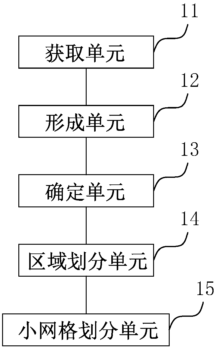
[0066] This embodiment relates to a device for creating a tire finite element model, such as figure 1 shown, including:
[0067] The obtaining unit 11 is configured to obtain a two-dimensional line drawing of component distribution on the tire axial section, where the two-dimensional line drawing of component distribution is specifically a line drawing of a tire material distribution map;
[0068] The forming unit 12 is used to distribute the lines of the two-dimensional line drawing according to the components to form sub-surfaces corresponding to the tire components, and each sub-surface corresponds to a layer covering a tire component. Specifically, the forming unit 12 is based on the sub-surface Create the corresponding number of layers and associate each subsurface with the corresponding layer. Tire components include tread, base tread, sidewall, belt, belt pad, carcass, crown , apex, bead, airtight layer and bead protector, correspondingly, the layers correspond to the ...
Embodiment 2
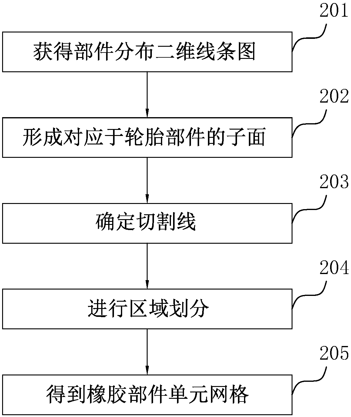
[0081] The difference between this embodiment and Embodiment 1 is that in this embodiment, the creation method of the tire finite element model is based on taking the tire wheel center as the origin, the tire axial direction as the first axis, that is, the Y axis, and the tire radial direction as the first axis. The coordinate system of the second axis is the X axis. According to the lines of the two-dimensional line drawing of the component parts distribution, the sub-surface corresponding to the tire component is formed, which specifically includes:
[0082] Determine the crown point of the tire according to the point coordinates on the boundary line of the tire tread in the two-dimensional line diagram of the component distribution. Specifically, by extracting the X coordinates of the points on the boundary line, the X coordinates of all points are compared to obtain tire crown point;
[0083] In the coordinate system, a two-dimensional line drawing covering the distributio...
Embodiment 3
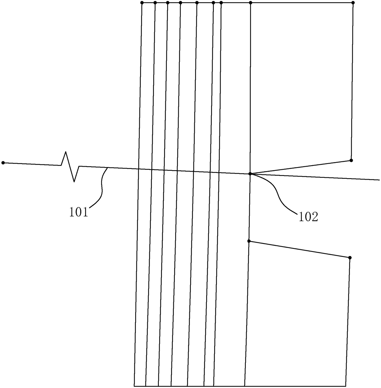
[0088] The difference between this embodiment and Embodiment 2 is that in this embodiment, in the method for creating a tire finite element model, based on the boundary lines and cutting lines 101 of each part in the two-dimensional line drawing of component distribution, each area is further The division of small grids that meet the requirements of predetermined grid quality parameters specifically includes:
[0089]Based on the boundary line and cutting line 101 of each part in the two-dimensional line drawing of the component distribution, further small grid division is performed on each area by using the small grid division parameters corresponding to each area;
[0090] Carry out quality inspection on the result of small grid division with predetermined grid quality parameters. When the result of small grid division does not meet the requirements of predetermined grid quality parameters, it will be re-performed with the new small grid division parameters corresponding to e...
PUM
 Abstract
Description
Claims
Application Information
 - R&D
- Intellectual Property
- Life Sciences
- Materials
- Tech Scout
- Unparalleled Data Quality
- Higher Quality Content
- 60% Fewer Hallucinations
Browse by: Latest US Patents, China's latest patents, Technical Efficacy Thesaurus, Application Domain, Technology Topic, Popular Technical Reports.
© 2025 PatSnap. All rights reserved.Legal|Privacy policy|Modern Slavery Act Transparency Statement|Sitemap|About US| Contact US: help@patsnap.com