Antenna structure and shape forming method applied to antenna structure

An antenna structure and antenna technology, applied in the field of communication, can solve problems such as difficult construction, large number of signal sources and antennas, and high wind pressure, so as to achieve the effect of improving flexibility and maximizing useful signal coverage

Inactive Publication Date: 2018-07-20
SHANGHAI DATANG MOBILE COMM EQUIP
View PDF4 Cites 4 Cited by
  • Summary
  • Abstract
  • Description
  • Claims
  • Application Information

AI Technical Summary

Problems solved by technology

There are many existing railway and highway tunnels in our country, and the difficulty of tunnel coverage lies in: the tunnel space is cylindrical, the vehicle travels fast, and the wind pressure formed is large; the surrounding rock walls are thick, and the external macro station cannot cover; the tunnels are narrow and long. , the scene is complex
[0006] 1. Leaky cable antenna: It is difficult and expensive to extend the continuous construction inside the tunnel. At the same time, due to the large transmission loss and coupling loss, the coverage distance of a leaky cable antenna connected to a signal source is about 1 kilometer.
[0007] 2. Small plate antennas and logarithmic periodic antennas: the antenna coverage distance is short, the number of sources and antennas that need to be consumed within a certain distance is large, and the deployment cost is high

Method used


Image

  • Antenna structure and shape forming method applied to antenna structure
  • Antenna structure and shape forming method applied to antenna structure
  • Antenna structure and shape forming method applied to antenna structure

Examples


Embodiment Construction

[0046] In order to make the above objects, features and advantages of the present invention more comprehensible, the present invention will be further described in detail below in conjunction with the accompanying drawings and specific embodiments.

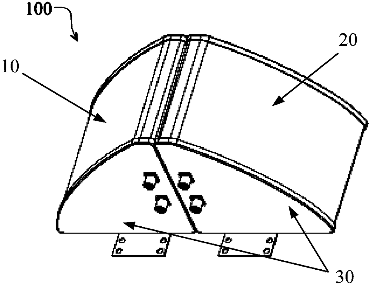
[0047] refer to figure 1 , showing a schematic diagram of an antenna structure according to an embodiment of the present invention, in figure 1 Middle: the antenna structure 100 includes a first cavity 10 and a second cavity 20 arranged symmetrically.

[0048] Wherein, the two ends of the first cavity 10 and the second cavity 20 are respectively provided with end caps 30 .

[0049] In an embodiment of the present invention, a first antenna body (not shown in the figure) is disposed in the first cavity 10, and the first antenna body is a narrow-beam high-gain antenna or a narrow-beam low-gain antenna.

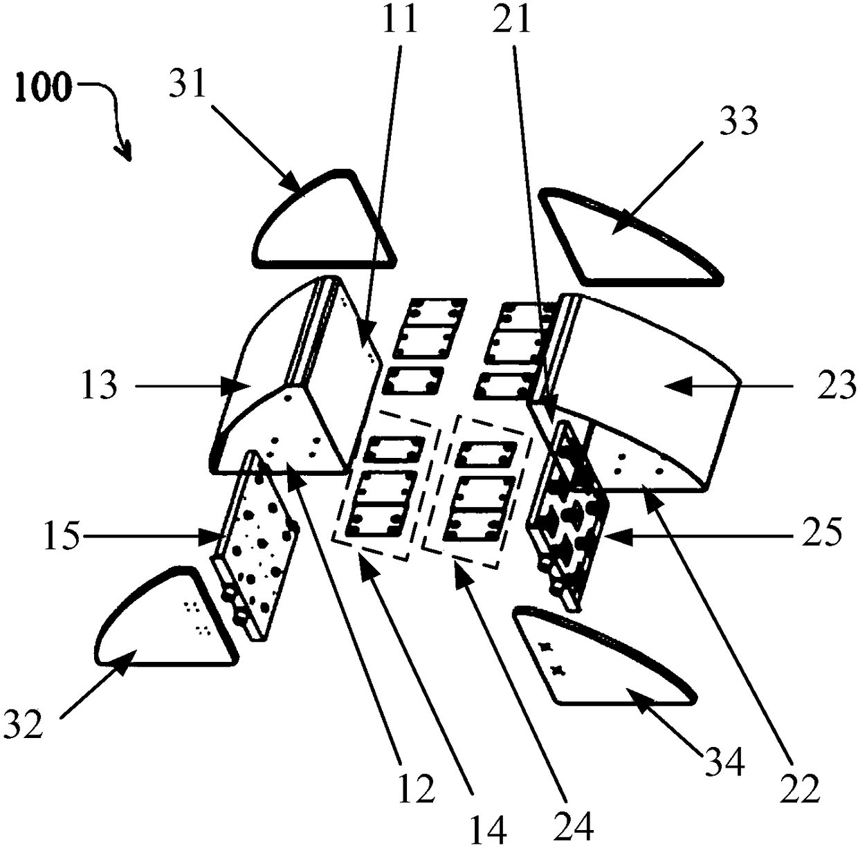
[0050] Specifically, such as figure 2 Shown is a specific structural schematic diagram of an antenna structure according to an...


PUM


Abstract

An embodiment of the invention provides an antenna structure and a shape forming method applied to the antenna structure. The antenna structure includes a first cavity and a second cavity arranged inmirror symmetry; and end covers mounted on two ends of the first cavity and the second cavity respectively, wherein the first cavity is therein provided with a first antenna body which is a narrow wave beam high gain antenna or a narrow wave beam low gain antenna. Therefore, antenna structure modularization is realized. a user can arrange the antenna body in the first cavity and the second cavityaccording to practical need, so that the antenna can meet demands of a tunnel scene better, maximization of a useful signal coverage range is realized and antenna mounting flexibility is improved effectively.

Description

technical field [0001] The embodiments of the present invention relate to the communication field, and in particular, to an antenna structure and a shaping method applied to the antenna structure. Background technique [0002] With the rapid development of wireless networks, the current user demand is to achieve full network coverage in all scenarios. The tunnel scene is one of the difficulties that need to be overcome in the process of achieving the goal of full coverage of the whole scene. There are many existing railway and highway tunnels in our country, and the tunnels are called covering difficulties. The problems lie in: the tunnel space is cylindrical, the vehicle travels fast, and the wind pressure formed is large; the surrounding rock walls are thick, and the external macro station cannot cover; the tunnels are narrow and long. , the scene is complex. [0003] The antennas of wireless devices in the prior art have a certain distance limit. When the distance excee...

Claims


Application Information

Patent Timeline
Patent Type & Authority Applications(China)
IPC IPC(8): H01Q1/36H01Q1/50H01Q3/34
CPCH01Q1/36H01Q1/50H01Q3/34
Inventor 李铁钧尚斋荣
Owner SHANGHAI DATANG MOBILE COMM EQUIP
Why Eureka
Try Eureka