Device and method for sending data after reconstruction of BBU and RRU functions

A data sending device and functional technology, applied in connection management, wireless communication, electrical components, etc., can solve the problems of unable to meet IQ signal capacity, limited transmission conditions, and unable to adopt networking solutions, etc., to reduce deployment costs and maintenance cost, efficient allocation of network resources, and the effects of fast and flexible network deployment

Active Publication Date: 2018-07-20
ZTE CORP
View PDF5 Cites 2 Cited by
  • Summary
  • Abstract
  • Description
  • Claims
  • Application Information

AI Technical Summary

Problems solved by technology

At the same time, the distance between the BBU and the RRU and the capacity of the IQ signal transmitted between the RRU are directly proportional to the system bandwidth and the number of antennas. When the system bandwidth is large and the number of antennas is large, optical fibers may not be able to meet the requirements. IQ signal capacity between BBU and RRU, or when there is no low-latency transmission condition between BBU and RRU, then the base station cannot adopt the networking scheme of separating BBU and RRU, and can only use the base station with integrated BBU and RRU
[0004] To sum up, the form and structure of the base station in the prior art is limited by the transmission conditions between the BBU and the RRU, which will cause inconsistencies in the networking flexible
At the same time, it increases the construction cost and maintenance cost of the network

Method used


Image

  • Device and method for sending data after reconstruction of BBU and RRU functions
  • Device and method for sending data after reconstruction of BBU and RRU functions
  • Device and method for sending data after reconstruction of BBU and RRU functions

Examples


Embodiment 1

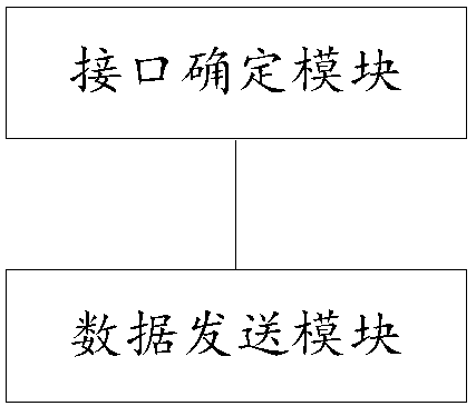
[0032] refer to image 3 As shown, it is a schematic structural diagram of a data sending device after the BBU and RRU functions are reconfigured according to an embodiment of the present invention, and the data sending device is set at a base station; in this embodiment, the data sending device includes:

[0033] an interface determining module, configured to determine the interface between the centralized unit and the distributed unit;

[0034] The data sending module is used to transmit the data packet processed by the centralized unit to the distribution unit through the interface, and the distribution unit continues to process it and then sends it to the receiving end.

[0035] Wherein, the centralized unit and the distributed unit are obtained by dividing all the functional modules of the base station, and all the functional modules of the base station are divided into a centralized unit and a plurality of distributed units, and the centralized unit includes multiple Fu...

Embodiment 2

[0058] refer to Figure 6 As shown, it is a flow chart of the data sending method after the BBU and RRU functions are reconstructed in the embodiment of the present invention. In this embodiment, the data sending method includes:

[0059] Step 101, determine the interface between the centralized unit and the distributed unit;

[0060] Step 102, transmit the data packet processed by the centralized unit to the distribution unit through the interface, and the distribution unit continues to process it and transmit it to the receiving end;

[0061] Wherein, the centralized unit and the distributed unit are obtained by dividing all the functional modules of the base station, and all the functional modules of the base station are divided into a centralized unit and a plurality of distributed units, and the centralized unit includes a plurality of functional units respectively corresponding to the plurality of distributed units , the functional modules contained in each distribution...

Embodiment approach

[0089] As a preferred implementation manner, the optional interface includes:

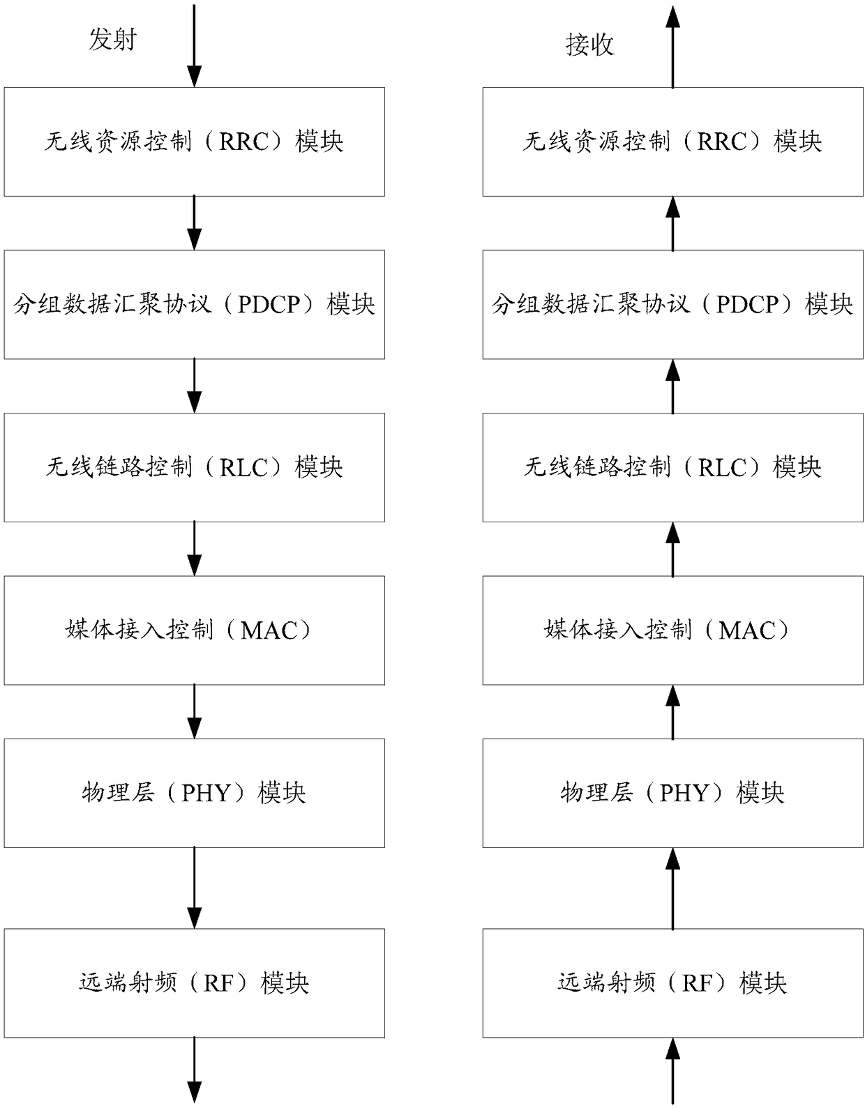
[0090] When the transmission conditions between the centralized unit and the distribution unit meet high delay and high capacity, the first-level interface or the second-level interface or the third-level interface is an alternative interface; when the transmission condition meets high delay and low For capacity, the second-level interface or the third-level interface is an optional interface; when the transmission conditions meet low latency and high capacity, the third-level interface is an optional interface.

[0091] As a preferred implementation manner, the optional interface includes:

[0092] When the transmission conditions between the centralized unit and the distributed unit meet high delay and high capacity, one or more of the following interfaces are optional interfaces: the interface between the first-level interface PHY module and the RF module, and the second interface The interface...


PUM


Abstract

The invention relates to a device and a method for sending data after reconstruction of BBU and RRU functions; the device for sending data comprises an interface determining module and a data sendingmodule, wherein the interface determining module is used for determining an interface between a centralized unit and a distribution unit; the data sending module is used for sending a data package processed by the centralized unit to the distribution unit through the interface and sending the data packet to a receiving end after being continuously processed by the distribution unit, wherein the centralized unit and the distribution unit are obtained by dividing all functional modules of a base station, all the functional modules of the base station are divided into a centralized unit and a plurality of distribution units, the centralized unit comprises a plurality of functional units which are in one-to-one correspondence with the distribution units, the functional modules contained in each distribution unit are different or the same, and the distribution units and the corresponding functional units jointly comprise all the base station functional modules. According to the device and the method, the functional modules can be flexibly divided between the centralized unit and the distribution units, so that rapid and convenient network deployment is realized.

Description

technical field [0001] The present invention relates to the technical field of wireless communication, and more specifically, to a data sending device and method after reconfiguration of BBU and RRU functions. Background technique [0002] In the existing wireless communication system, the base station is divided into a baseband processing unit (BBU) and a remote radio frequency processing unit (RRU). The baseband processing unit mainly completes the processing functions of baseband signals, including coding, modulation, signaling processing and other functions. The remote radio frequency processing unit mainly completes the processing functions from baseband signal to radio frequency signal, including digital / analog conversion, filtering, amplification and other functions. The IQ (Inphase and quadrature) signal is transmitted between the BBU and the RRU. The CPRI (Common Public Radio Interface) interface or the OBSAI (OpenBase Station Architecture Initiative) interface can ...

Claims


Application Information

Patent Timeline
Patent Type & Authority Applications(China)
IPC IPC(8): H04W76/27H04W88/08H04W92/12
CPCH04W88/085H04W92/12
Inventor 李楠黄河高音张丽
Owner ZTE CORP
Why Eureka
Try Eureka